Chinese Physics Letters, 2021, Vol. 38, No. 7, Article code 074202 A Self-Diffraction Temporal Filter for Contrast Enhancement in Femtosecond Ultra-High Intensity Laser Xian-Zhi Wang (王羡之)1,2, Zhao-Hua Wang (王兆华)1,4*, Yuan-Yuan Wang (王媛媛)1,2, Xu Zhang (张旭)1,2, Jia-Jun Song (宋贾俊)1,2, and Zhi-Yi Wei (魏志义)1,2,3* Affiliations 1Beijing National Laboratory for Condensed Matter Physics, Institute of Physics, Chinese Academy of Sciences, Beijing 100190, China 2University of Chinese Academy of Sciences, Beijing 100049, China 3Songshan Lake Materials Laboratory, Dongguan 523808, China 4CAS Center for Excellence in Ultra-intense Laser Science, Shanghai 201800, China Received 16 March 2021; accepted 6 May 2021; published online 3 July 2021 Supported by the National Natural Science Foundation of China (Grant Nos. 11774410 and 91850209), and the Strategic Priority Research Program of CAS (Grant No. XDB16030200).
*Corresponding authors. Email: zhwang@iphy.ac.cn; zywei@iphy.ac.cn
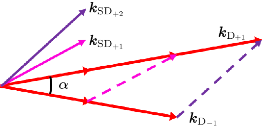
Citation Text: Wang X Z, Wang Z H, Wang Y Y, Zhang X, and Song J J et al. 2021 Chin. Phys. Lett. 38 074202    Abstract We demonstrated a nonlinear temporal filter based on the self-diffraction (SD) process. Temporal contrast enhancement, angular dispersion and spectrum broadening properties of the SD process are investigated in experiment and simulation. Driven by spectral phase well compensated laser pulses with bandwidth of 28 nm, the filter produced clean pulses with a temporal contrast higher than $10^{10}$ and excellent spatial profile, the spectrum of which was smoothed and broadened to 64 nm. After implementing this filter into a home-made 30 TW Ti:sapphire amplifier, temporal contrast of the amplified pulses was enhanced to $10^{10}$ within the time scale of $-400$ ps. DOI:10.1088/0256-307X/38/7/074202 © 2021 Chinese Physics Society Article Text The invention of chirped-pulse amplification (CPA) technology[1] has led to a dramatic increase of laser intensity since the 1980s. Along with titanium-doped sapphire (Ti:sapphire), ultra-short laser pulses with peak powers of multi-petawatt[2–5] and intensities up to 10$^{22}$–10$^{24}$ W/cm$^{2}$ (Refs. [6–9]) have been generated and planned in small-scale laboratories, which have become powerful experimental facilities for investigation of laser matter interaction in the relativistic regimes. Due to the fact that solid targets will be ionized by any undesired pulse with intensity higher than 10$^{11}$ W/cm$^{2}$ ahead of the main pulse, which would greatly affect laser-plasma interaction,[10] temporal contrast is one of the most important parameters for such high intensity laser pulses. As for the temporal contrast, amplified spontaneous emission (ASE)[11] and pre-pulses[12] are two major challenges. To mitigate the negative impact of ASE, several techniques have been developed to suppress it, such as double CPA (DCPA),[13] saturable absorbers,[14] optical parametric amplification (OPA),[15] and cross-polarized wave generation (XPW).[16] The XPW filter has been widely used because of its compact setup as well as spectral broadening effect, but the performance of temporal contrast enhancement is limited by the extinction ratio of the polarizer that separates the XPW signal from input pulses. However, the ability of the self-diffraction (SD) process to generate clean femtosecond laser pulses with high temporal contrast has been reported recently,[17,18] though SD was mostly studied in pulse duration measurement.[19,20] SD is also a third-order nonlinear effect like XPW, but produces clean pulses in a different direction from the incident pulses. The absence of polarizing components implies that SD has the potential to reduce ASE by large orders of magnitude and it could be a promising technique for generation of ultra-high intensity laser pulses with high temporal contrast. In this work, temporal cleaning and spectral broadening properties of the SD process are discussed, simulated and experimentally investigated, with the angular dispersion also mentioned. A nonlinear temporal filter based on the SD process was demonstrated. Driven by our home-built Ti:sapphire CPA laser, this filter produced clean pulses with a good beam profile, energy of 35 µJ and spectrum bandwidth exceeding 60 nm (full width at half maximum, FWHM). The picosecond temporal contrast was enhanced more than four orders of magnitude to 10$^{10}$. To testify its practicability, the temporal filter was further applied into a DCPA system, which generated 0.9 J pulses with pulse duration as short as 29.7 fs, and temporal contrast of 10$^{10}$. When two pulses D$_{+1}$ and D$_{-1}$ overlap each other temporally and spatially in a thin plate of nonlinear material, an interference pattern occurs. If the intensity of input pulses is high enough, the constructive interference will induce a change in refractive index of the material by the Kerr effect, while the destructive interference will not. The thin plate with periodically spaced different refractive indices acts like a transmission grating and diffracts the input pulses. Because it is a Kerr effect related phenomenon, it is also a third order nonlinear optical effect. The phase matching condition is illustrated in Fig. 1, which could be expressed as $$ {\boldsymbol k}_{{\rm SD}_{\pm m}} =({m+1}){\boldsymbol k}_{{\rm D}_{\pm 1}}-m{\boldsymbol k}_{{\rm D}_{\mp 1}},~~ \tag {1} $$ where ${\boldsymbol k}$ is the wave vector, and $m$ is the order number of the SD process. When the crossing angle $\alpha$ is small enough, the magnitude of ${\boldsymbol k} _{{\rm SD}_{+1}}$ is approximately equal to that of ${\boldsymbol k} _{{\rm D}_{+1}}$ and ${\boldsymbol k} _{{\rm D}_{-1}}$, which means that the SD process is a nearly degenerate four-wave mixing process. Thus, the temporal and spatial walk-off are negligible in a fused silica plate thinner than 1 mm, with input pulse duration at several tens of femtoseconds and crossing angle smaller than 2$^{\circ}$.
cpl-38-7-074202-fig1.png
Fig. 1. The phase matching of SD process.
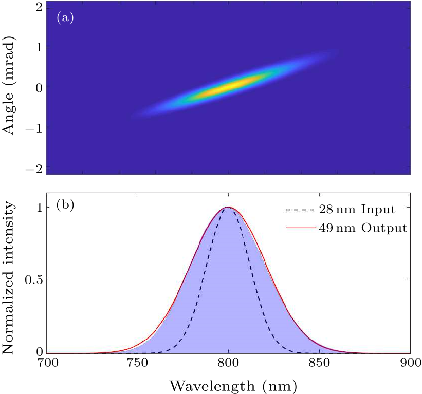
The intensity of first-order SD signal can be expresses as $I_{{\rm SD}_{+1}} \propto I_{{\rm D}_{+1}}^{2} (t)I_{{\rm D}_{-1}} ({t-\tau })$. To prevent filamentation, the total energy of D$_{+1}$ and D$_{-1}$ is usually limited. The above equation implies that the intensity of the SD$_{+1}$ signal is proportional to the cubic input pulse intensity. This means that the pre-pulse and ASE with lower intensity will be suppressed due to a much lower conversion, and the temporal contrast of the SD$_{+1}$ signal is the cube of contrast of input pulse in theory. Moreover, the SD signal is diffracted into a different direction from the input pulse. Therefore, the SD process has great potential for temporal contrast enhancement which is not limited by the extinction ratio of polarization components. It has been reported that there is angular dispersion in the SD$_{+1}$ signal,[21] originating from phase matching in the non-collinear geometry. More importantly, the spectrum of the SD$_{+1}$ signal will be broader than that of the input pulse. To give an example, for a femtosecond laser pulse with spectrum width (FWHM) of tens of nanometers as the input pulse, with ${\boldsymbol k} _{{\rm D}_{+1}}$ or ${\boldsymbol k} _{{\rm D}_{-1}}$ at different wavelengths, the wavelength and direction of ${\boldsymbol k} _{{\rm SD}_{+1}}$ are different, which results in angular dispersion. Assuming that ${\boldsymbol k} _{{\rm D}_{+1}}$ is the wave vector of the shortest wavelength component, and ${\boldsymbol k} _{{\rm D}_{-1}}$ is the longest wavelength component, it is easy to see that the ${\boldsymbol k} _{{\rm SD}_{+1}}$ represents a wavelength shorter than the shortest wavelength of the input pulse, thusly the spectrum is broadened. Simulations were conducted from Eq. (1) with parameters close to the experimental condition, in which the central wavelength of the Fourier transform limited input pulse is 800 nm with FWHM of 28 nm and the cross angle of ${\boldsymbol k} _{{\rm D}_{+1}}$ and ${\boldsymbol k} _{{\rm D}_{-1}}$ is 0.5$^{\circ}$. Figure 2(a) is the relation between output angle and wavelength of the SD$_{+1}$ signal, which indicates that the angular dispersion is mostly linear. In Fig. 2(b), the blue area is the angle-integrated spectrum of the SD$_{+1}$ signal. The black dashed line represents the spectrum of the input pulse, the FWHM of which is 28 nm. The red solid curve is a Gaussian distribution with FWHM of 49 nm, which is drawn as a comparison to show the slightly asymmetry and blue shift of the SD$_{+1}$ spectrum. The spectrum is broadened by a factor about 1.73 in the SD process.
cpl-38-7-074202-fig2.png
Fig. 2. Spectral properties of SD signal calculated from the phase matching condition. The spectrum width of input pulse is 28 nm and the cross angle of ${\boldsymbol k} _{{\rm D}_{+1}}$ and ${\boldsymbol k} _{{\rm D}_{-1}}$ is 0.5$^{\circ}$. (a) Angular dispersion of the SD$_{+1}$ pulse. (b) Spectrum of the SD$_{+1}$ pules. Blue area: the angle-integrated spectrum from (a). Red solid curve: output spectrum with Gaussian distribution of 49 nm FWHM. Black dashed curve: input spectrum with Gaussian distribution of 28 nm FWHM
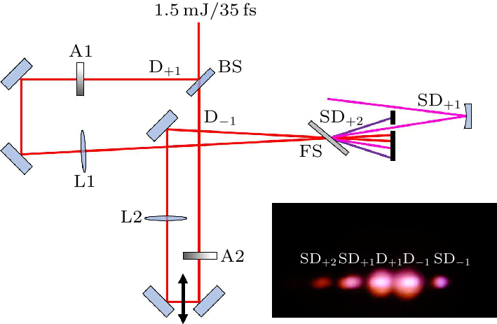
The detailed structure of the SD temporal filter is illustrated in Fig. 3. In the experiment, the 1.5 mJ driving pulse with pulse duration of 35 fs came from the CPA system mentioned in our previous work,[22] and was split by a beam splitter BS. D$_{+1}$ and D$_{-1}$ were the reflected and transmitted beams, respectively, which both passed through an attenuator (A1 and A2) to adjust the energy. To prevent filamentation and to maximize the output of SD$_{+1}$, the energies of D$_{+1}$ and D$_{-1}$ on the glass plate were adjusted to 300 µJ and 200 µJ, respectively. After being focused by two lenses with $1-m$ focal length, D$_{+1}$ and D$_{-1}$ coincided with each other on a 0.4-mm-thick fused silica plate with the incidence angle at the Brewster angle. By placing the fused silica plate 50 mm after the focal point, the beam diameters on the fused silica were both around 800 µm at $1/e^2$. The peak power density at the glass plate was estimated to be $2.8 \times 10^{12}$ W/cm$^2$. The crossing angle between D$_{+1}$ and D$_{-1}$ was about 0.5$^{\circ}$. When the incident pulses were temporally synchronized by finely tuning a motor-controlled stage with 100 nm/step, the interference pattern of the incident beams appeared, as well as SD signals on both sides of D$_{+1}$ and D$_{-1}$. As shown in Fig. 3, D$_{+1}$ and D$_{-1}$ are the residual incident pulses, SD$_{+1}$ and SD$_{-1}$ are the first order SD signals. The SD$_{2}$ signal and higher order SD signal could also be seen. The SD$_{+1}$ pulse was delivered through an aperture before being collimated by a spherical concave mirror with radius of curvature of 950 mm, while the other pulses were blocked. Under this condition, the energy of the SD$_{+1}$ pulse reached 35 µJ, which could be used as a high temporal contrast seed. The energy conversion efficiency from the incident pulses to the SD$_{+1}$ signal is 7%, and the power stability of the SD$_{+1}$ signal is about 2.5% RMS in three hours.
cpl-38-7-074202-fig3.png
Fig. 3. Detailed structure of the SD pulse cleaner. The inset is the photo of generated SD signals and residual incident pulses. BS: beam splitter. A1, A2: attenuator. L1, L2: lens. FS: fused silica.
cpl-38-7-074202-fig4.png
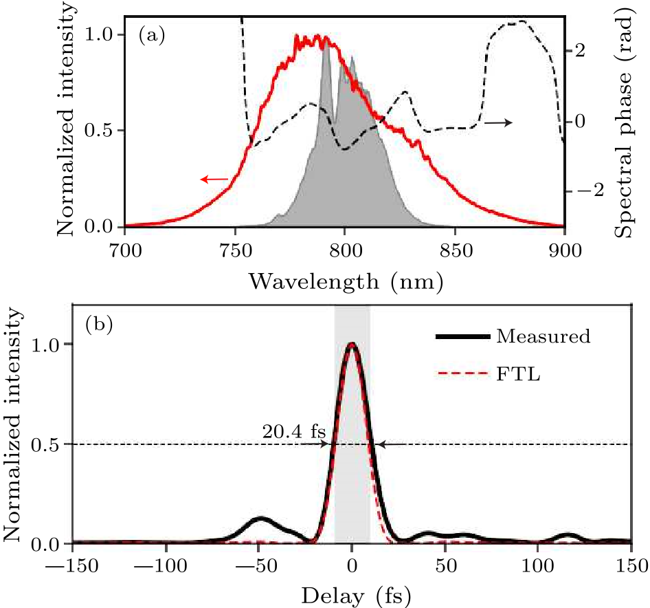
Fig. 4. (a) The spectrum of SD$_{+1}$ signal was smoother and broader than that of incident pulses. Shaded area: the spectrum of incident pulses. Red line: the spectrum of the SD$_{+1}$ signal. Black dashed line: the spectral phase of the SD$_{+1}$ signal after a pair of chirp mirrors which provides $-80$ fs$^{2}$ of GDD. (b) The pulse duration of the SD$_{+1}$ signal after a pair of chirp mirrors which provides $-80$ fs$^{2}$ of GDD.
As shown in Fig. 4(a), the spectral bandwidth of the SD$_{+1}$ pulse was 64 nm, while it was 28 nm for the input pulse. The broadening factor had a strong dependence on the residual spectral phase of the input pulse, and was larger in experiment than that in calculation because there was also a self-phase modulation (SPM) effect while propagating through the glass plate, which could further broaden the spectrum. The broader spectrum was good for obtaining shorter pulse duration after amplification. The pulse duration of SD$_{+1}$ was measured by a self-referenced spectral interferometer (Wizzler, Fastlite Inc.) after compression by a pair of chirp mirrors providing $-80$ fs$^{2}$ of group delay dispersion (GDD) in total, which was 20.4 fs, as illustrated in Fig. 4(b).
cpl-38-7-074202-fig5.png
Fig. 5. (a) The temporal contrast of SD$_{+1}$ signal. (b) The spatial quality of SD$_{+1}$ signal.
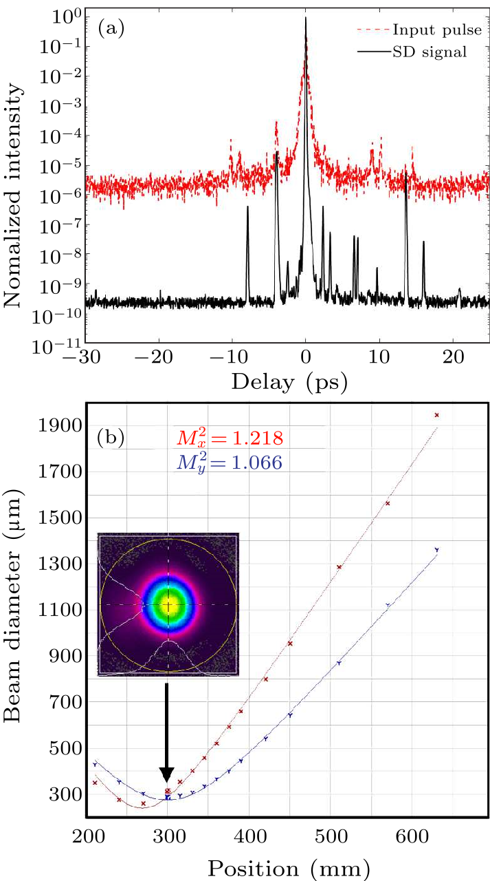
It has been reported that the SD process can suppress the pre-pulse and improve the temporal contrast of the input pulse in nanosecond range.[23] The temporal contrast within picosecond scale of the SD$_{+1}$ pulse was measured utilizing a third-order cross correlator (Sequoia 800, Amplitude Technologies). In Fig. 5(a), the red dashed line shows the temporal contrast of the input pulse, which was about 10$^{6}$. The black line represents the contrast of the SD$_{+1}$ pulse, which was about 10$^{10}$. The temporal contrast was improved by more than four orders of magnitude and the pre-pulses were also suppressed by several orders of magnitude. By significantly reducing the ASE level, some pre-pulses that had been buried by ASE could also be detected. However, the contrast should have been still 1–2 orders of magnitude better, because the energy of the SD$_{+1}$ pulse was not enough to realize a higher dynamic range, and the ASE level in Fig. 5(a) was the detection limit. Apart from the good temporal parameters, the spatial quality was also improved. Because the higher order transverse mode exhibits worse focusing ability, the high spatial frequency components would have a larger beam diameter on the fused silica and contribute less during the SD process, which improves the spatial quality. The $M^{2}$ factor of SD$_{+1}$ signal was measured as shown in Fig. 5(b), in which the blue line represents $M^{2}$ for the horizontal axis, and the red line for the vertical one. Because of the angular dispersion, the $M^{2}$ in horizontal direction was not as good as that in the vertical direction. The far-field beam profile is shown in the inset of Fig. 5(b).
cpl-38-7-074202-fig6.png
Fig. 6. Schematic diagram of the whole DCPA system.
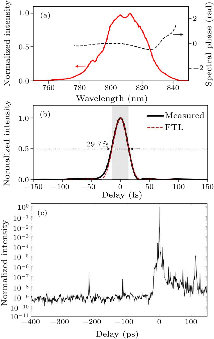
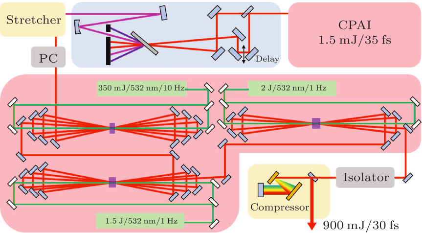
To testify the practicability of the SD filter, the SD$_{+1}$ pulse without compression was injected into another home-built CPA system as a high temporal contrast and broadband seed. The schematic diagram is illustrated in Fig. 6. For amplification, one major issue of the SD$_{+1}$ pulse was the angular dispersion. As calculated above, angular dispersion of the SD$_{+1}$ pulse is mostly linear, and the compensation of which by a single prism has been reported.[21] However, Martinez stretcher could also induce angular dispersion if misaligned.[24] Hence, slightly and properly adjusting the distance between the concave mirror and the flat mirror in the stretcher of the second CPA stage would compensate for the angular dispersion of the SD$_{+1}$ pulse. As was reported, there is only a small amount of residual high order angular dispersion after the linear part has been compensated for.[21] During further amplification stages, the influence of wavefront aberration caused by large aperture amplification and transmissive elements will have greater influence on focusing characteristics than the residual high order angular dispersion, which should be compensated for by deformable mirrors. The stretched pulse was firstly introduced into a 6-pass amplifier, which was pumped by a 350 mJ Nd:YAG laser at 10 Hz. The output energy was about 50 mJ. In the second 6-pass amplifier, the energy was boosted to 510 mJ using pump laser with energy of 1.5 J at 1 Hz. In the 4-pass amplifier, the pump energy was 2 J with the output energy of 1.2 J and standard deviation of 16 mJ (1.3%) for 8000 consecutive shots. After the Faraday isolator, the beam was enlarged to 40 mm diameter and finally sent into the vacuum compressor. The measured spectral intensity and phase of the compressed pulse was illustrated in Fig. 7(a), with pulse duration of 29.7 fs as shown in Fig. 7(b). The output energy was 0.9 J, leading to a peak power of 30 TW. In Fig. 7(c), the contrast at the output of the laser system is presented, which was around 10$^{10}$ within the time scale of $-400$ ps. It could be noticed that the pre-pulse at $-114$ ps was the artifact from the relatively strong post pulse at 114 ps behind the main pulse, which originated from the double reflection at the two faces of the Glan polarizer in the amplifier.
cpl-38-7-074202-fig7.png
Fig. 7. (a) The spectrum of the compressed pulse. Black dashed line: residual spectral phase of compressed pulse. (b) Pulse duration of the compressed pulse. (c) Temporal contrast of the amplified pulse.
In summary, the phase matching and spectral-temporal properties, including temporal contrast enhancement, angular dispersion and spectrum broadening, have been discussed and simulated. A nonlinear temporal filter based on the SD process was developed, which enhanced the temporal contrast of input pulses by more than four orders of magnitude to 10$^{10}$. Moreover, the filter broadened the spectrum and improved the spatial quality of input pulses. After implementing the filter into a DCPA laser system, 30 fs pulses with contrast of 10$^{10}$ were generated at the peak power level of 30 TW. The results show that SD process is a competitive alternative among several methods for high temporal contrast seed generation. It could not only provide good contrast enhancement performance due to the abandonment of polarizing components, but also broaden the spectrum to obtain a shorter pulse duration after amplification. The angular dispersion issue from phase matching could be mitigated by the second stretcher in DCPA architecture. This filter could be an ideal pulse cleaning module in high contrast DCPA laser facilities for the study of high field physics such as plasma high harmonics generation and laser plasma acceleration.
References Compression of amplified chirped optical pulsesHigh-contrast 116 PW Ti:sapphire laser system combined with a doubled chirped-pulse amplification scheme and a femtosecond optical-parametric amplifier42 PW, 20 fs Ti:sapphire laser at 01 Hz339 J high-energy Ti:sapphire chirped-pulse amplifier for 10 PW laser facilityHigh-energy hybrid femtosecond laser system demonstrating 2 × 10 PW capabilityImprovement of the focusing ability by double deformable mirrors for 10-PW-level Ti: sapphire chirped pulse amplification laser systemHigh-contrast high-intensity repetitive petawatt laserAchieving the laser intensity of 55×10 22 W/cm 2 with a wavefront-corrected multi-PW laserCurrent status and highlights of the ELI-NP research programExperimental investigation on the temporal contrast of pre-pulses by post-pulses in a petawatt laser facilityAmplified spontaneous emission in a Ti:sapphire regenerative amplifierContrast degradation in a chirped-pulse amplifier due to generation of prepulses by postpulsesDouble chirped-pulse-amplification laser: a way to clean pulses temporallySuppression of the amplified spontaneous emission in chirped-pulse-amplification lasers by clean high-energy seed-pulse injectionContrast enhancement in a Ti:sapphire chirped-pulse amplification laser system with a noncollinear femtosecond optical-parametric amplifier10^?10 temporal contrast for femtosecond ultraintense lasers by cross-polarized wave generationTemporal contrast enhancement of femtosecond pulses by a self-diffraction process in a bulk Kerr mediumTemporal contrast improvement based on the self-diffraction process with a cylinder mirrorSelf-diffraction: A new method for characterization of ultrashort laser pulsesCharacterization of arbitrary femtosecond pulses using frequency-resolved optical gatingLinear angular dispersion compensation of cleaned self-diffraction light with a single prismSpectral-Phase-Modulated Cross-Polarized Wave for Chirped Pulse Amplifier with High Contrast RatioSuppression of prepulses by a temporal pulse cleaner based on a self-diffraction process for an ultraintense femtosecond laserSpatial Spectrum Chirp Characteristic of a Martinez-Type Multipass Pulse Stretcher
[1] Strickland D and Mourou G 1985 Opt. Commun. 55 447
[2] Wang Z, Liu C, Shen Z, Zhang Q, Teng H, and Wei Z 2011 Opt. Lett. 36 3194
[3] Sung J H et al. 2017 Opt. Lett. 42 2058
[4] Li W et al. 2018 Opt. Lett. 43 5681
[5] Lureau F et al. 2020 High Power Laser Sci. Eng. 8 E43
[6] Guo Z et al. 2018 Opt. Express 26 26776
[7] Kiriyama H et al. 2018 Opt. Lett. 43 4595
[8] Yoon J W, Jeon C, Shin J, Lee S K, Lee H W, Choi I W, Kim H T, Sung J H, and Nam C H 2019 Opt. Express 27 20412
[9] Tanaka K A et al. 2020 Matter Radiat. Extremes 5 024402
[10] Kiriyama H, Miyasaka Y, Sagisaka A, Ogura K, Nishiuchi M, Pirozhkov A S, Fukuda Y, Kando M, and Kondo K 2020 Opt. Lett. 45 1100
[11] Ivanov V V, Maksimchuk A, and Mourou G 2003 Appl. Opt. 42 7231
[12] Didenko N V, Konyashchenko A V, Lutsenko A P, and Tenyakov S Y 2008 Opt. Express 16 3178
[13] Kalashnikov M P, Risse E, Schönnagel H, and Sandner W 2005 Opt. Lett. 30 923
[14] Itatani J, Faure J, Nantel M, Mourou G, and Watanabe S 1998 Opt. Commun. 148 70
[15] Liu C, Wang Z, Li W, Zhang Q, Han H, Teng H, and Wei Z 2010 Opt. Lett. 35 3096
[16] Jullien A et al. 2005 Opt. Lett. 30 920
[17] Liu J, Okamura K, Kida Y, and Kobayashi T 2010 Opt. Express 18 22245
[18] Li F, Shen X, Wang P, Li Y, Liu J, Wang Z, and Li R 2016 Laser Phys. Lett. 13 055303
[19] Nighan W L, Gong T, Liou L, and Fauchet P M 1989 Opt. Commun. 69 339
[20] Kane D J and Trebino R 1993 IEEE J. Quantum Electron. 29 571
[21] Shen X, Wang P, Liu J, and Li R 2018 High Power Laser Sci. Eng. 6 e23
[22] Qin S, Wang Z H, Yang S S, Shen Z W, Dong Q L, and Wei Z Y 2017 Chin. Phys. Lett. 34 024205
[23] Xie N, Zeng X, Wang X, Zhou K, Sun L, Zuo Y, Huang X, and Su J 2019 Optik 178 279
[24] Ohmae G, Yagi T, Nanri K, and Fujioka T 2000 Jpn. J. Appl. Phys. 39 5864