Chinese Physics Letters, 2022, Vol. 39, No. 3, Article code 034201 Nonlinear Generation of Perfect Vector Beams in Ultraviolet Wavebands Hui Li (李慧)1,2†, Haigang Liu (刘海港)2†, Yangfeifei Yang (杨洋飞飞)2, Ruifeng Lu (陆瑞锋)1*, and Xianfeng Chen (陈险峰)2,3,4,5* Affiliations 1Institute of Ultrafast Optical Physics, Department of Applied Physics & MIIT Key Laboratory of Semiconductor Microstructure and Quantum Sensing, Nanjing University of Science and Technology, Nanjing 210094, China 2State Key Laboratory of Advanced Optical Communication Systems and Networks, School of Physics and Astronomy, Shanghai Jiao Tong University, Shanghai 200240, China 3Shanghai Research Center for Quantum Sciences, Shanghai 201315, China 4Jinan Institute of Quantum Technology, Jinan 250101, China 5Collaborative Innovation Center of Light Manipulations and Applications, Shandong Normal University, Jinan 250358, China Received 25 November 2021; accepted 14 January 2022; published online 1 March 2022 These authors contributed equally to this work.
*Corresponding authors. Email: rflu@njust.edu.cn; xfchen@sjtu.edu.cn
Citation Text: Li H, Liu H G, Yang Y F F et al. 2022 Chin. Phys. Lett. 39 034201    Abstract Perfect vector beams are a class of special vector beams with invariant radius and intensity profiles under changing topological charges. However, with the limitation of current devices, the generation of these vector beams is limited in the visible and infrared wavebands. Herein, we generate perfect vector beams in the ultraviolet region assisted by nonlinear frequency conversion. Experimental and simulation results show that the radius of the generated ultraviolet perfect vector beams remains invariant and is thus independent of the topological charge. Furthermore, we measure the power of the generated ultraviolet perfect vector beams with the change of their topological charges. This study provides an alternative approach to generating perfect vector beams for ultraviolet wavebands and may promote their application to optical trapping and optical communication.
cpl-39-3-034201-fig1.png
cpl-39-3-034201-fig2.png
cpl-39-3-034201-fig3.png
cpl-39-3-034201-fig4.png
DOI:10.1088/0256-307X/39/3/034201 © 2022 Chinese Physics Society Article Text Polarization, as a salient feature of light beams, is of great importance in influencing the interaction of light and matter. Homogeneously polarized beams, such as linearly polarized beams, circularly polarized beams, and elliptically polarized beams, have been widely studied in various fields. In recent years, beams with space-variant polarization distributions, known as vector beams, have elicited widespread interest because of their many specific features, such as strong nonvanishing longitudinal field under diffraction limit,[1] optical chain,[2] and optical cages[3,4] when tightly focused. Conventionally, cylindrical vector beams are a subclass of vector beams with axially symmetric intensity and polarization profiles across transverse sections. Such vector beams have sparked considerable interest for applications ranging from classical to quantum physics.[5,6] The typical paradigms include azimuthally, radially, and spiral polarized beams.[7–9] Vector beams with a nonuniform polarization state across their profiles can be represented by modified high-order Poincaré beams,[10–12] which are widely used in areas such as imaging encryption.[13,14] To date, many methods have been developed to generate vector beams. Among them, cylindrical vector beams can be generated by using metamaterials,[15,16] q-plate,[8] spatial light modulator,[7,17,18] s-waveplates,[19] glass cone,[20] and geometric phase[21] or by the coherent superposition of two orthogonally polarized beams.[22] On the contrary, noncylindrical symmetric beams have been demonstrated by employing biaxial crystals or the combination of cylindrical lens and half waveplates.[23] These techniques rely on the modulation of the wave front of the optical field. Recently, the interaction of spin and orbit angular momentum has also provided a flexible way to generate vector beams.[24,25] As a new type of vector beam, perfect vector (PV) beams have been proposed and investigated over the last decade, and they have been characterized as having radii that are independent of topological charges. Researchers have also experimentally demonstrated the generation of individual and arrays of PV beams with stable intensity profiles and polarization distributions at certain propagation distances on the basis of geometric phase and liquid crystal devices.[14,26–30] An efficient method is femtosecond laser fabrication that has been employed to generate perfect vortex beams.[31] Moreover, integer and fractional ellipse PV beams and nonring-shaped PV beams have been efficiently generated.[32–34] Unfortunately, the spectral limitations of these devices and techniques restrict the generation of PV beams in the ultraviolet wavelength range, which would further expand the applications of microscopy and spectroscopy down to the nanometer scale. In addition, the generation of PV beams in ultraviolet wavebands may promote applications of optical communication with large topological charges and the optical trapping of fixed trajectories in the ultraviolet realm. As a promising approach, the combination of nonlinear frequency conversion and vector beams brings extremely interesting phenomena. In previous research, the nonlinear generation of vector beams is studied on the basis of second harmonic (SH) generation and three-wave mixing.[35–38] In the present study, we theoretically and experimentally demonstrate the generation of PV beams in ultraviolet wavebands. The generation process is driven by an infrared Bessel vortex beam and a green Gaussian beam that is generated through SH generation. In the experiment, the ultraviolet PV beams with topological charges $l = 1,\, 2,\, 3$ are generated, and their vector properties are measured. The results show that the radii of the generated ultraviolet PV beams remain invariant and are independent of the topological charges. We also measure the power variation trend of the generated ultraviolet PV beams with the increase of the topological charges.
cpl-39-3-034201-fig1.png
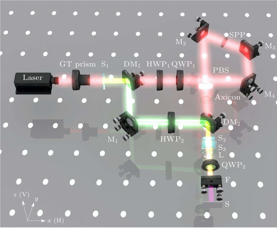
Fig. 1. Schematic of experimental setup. GT prism: Glan–Taylor prism; S$_{1}$: 5 mol% MgO:LiNbO$_{3}$; DM$_{1}$ and DM$_{2}$: dichroic mirror; HWP$_{1}$ and HWP$_{2}$: half waveplates operating at 1064 and 532 nm, respectively; QWP$_{1}$ and QWP$_{2}$: quarter waveplates with operating wavelengths of 1064 and 355 nm, respectively; PBS: polarized beam splitter; M$_{1}$, M$_{2}$, M$_{3}$, and M$_{4}$: mirrors; SPP: spiral phase plate; S$_{2}$, S$_{3}$: potassium dihydrogen phosphate (KDP) crystals; F: filter; S: screen. V and H in the lower left corner denote the vertical and horizontal directions, respectively.
The experimental setup is displayed in Fig. 1. A high-energy diode-pumped all-solid-state Q-switched laser delivers linearly polarized 10 ns pulses at a wavelength of 1064 nm and at a 1 kHz repetition rate. A Glan–Tylor (GT) prism is used to adjust the polarization direction and intensity of the fundamental frequency (FF) beam. A half waveplate (HWP$_{1}$) combined with a quarter waveplate (QWP$_{1}$) allows us to rotate the polarization direction of the FF beam. Then, the two orthogonally polarized components of the FF beams pass through a Sagnac interferometer consisting of three mirrors (M$_{2}$, M$_{3}$, and M$_{4}$), a polarized beam splitter (PBS), and a spiral phase plate (SPP). As a result, the electric field of the FF beam can be written as the superposition of two counter-propagating beams: $$\begin{align} E_{\rm FF}({\rho,\phi})={}&A_{1}\{\exp[{i({l\phi +\beta +2\gamma})}]\hat{e}_{x}\\ &+{i\exp[{-i({l\phi +2\gamma})}]\hat{e}_{y}}\},~~ \tag {1} \end{align} $$ where $E_{\rm FF}(\rho$,$\phi$) denotes the FF beams with a wavelength of 1064 nm in the cylindrical coordinate system; $A_{1}$ is the amplitude transverse profile of the FF beam; $l$ and $\phi$ represent the topological charge of the SPP and the azimuthal angle of the beam cross section, respectively; $\beta$ describes the phase difference between two orthogonal components caused by the Sagnac interferometer; $\gamma$ is the angle of the fast axis of HWP$_{1}$ with respect to the horizontal direction; and $\hat{e}_{x}$ and $\hat{e}_{y}$ refer to the Cartesian unit vectors corresponding to the horizontal and vertical polarizations, respectively. An axicon with a base angle of 2$^{\circ}$ is used to convert the FF beams to the Bessel beams on the basis of the following expression: $$ \begin{alignat}{1} E_{\rm FF}({\rho,\phi})={}&A_{1}\{\exp[{i({l\phi +\beta +2\gamma})}]\hat{e}_{x} \\ &+{i\exp[{-i({l\phi +2\gamma})}]\hat{e}_{y}}\}J_{l}({k_{\rm r} \rho}),~~ \tag {2} \end{alignat} $$ where $J_{l}$ denotes the first kind of Bessel beam and $k_{\rm r}$ is the wave vector along the radial direction. To achieve the ultraviolet beams, a homogenous 5 mol% MgO:LiNbO$_{3}$ crystal (S$_{1}$) is inserted between the GT prism and the dichroic mirror (DM$_{1}$). S$_{1}$ is cut for the type-I phase matching (oo-e) condition. As a result, the generated SH beams can be expressed as $E_{\rm SH}({\rho,\phi})=A_{2}[{\hat{e}_{x} +\hat{e}_{y}}]$, where $A_{2}$ is the amplitude of the SH beams and has a Gaussian profile. A reflector M$_{1}$ and DM$_{2}$ are used to combine the generated SH and FF beams. HWP$_{2}$ is added to adjust the polarization direction of the SH beams. The up-conversion source is formed by two potassium dihydrogen phosphate (KDP) crystals (S$_{2}$, S$_{3}$). The cut angle between the optical axis of the KDP crystals (S$_{2}$ and S$_{3}$) and the propagation is fixed at 57.3$^{\circ}$ to fulfill the type-II (eo-e) phase matching condition. S$_{2}$ and S$_{3}$ are placed in two orthogonal directions. S$_{2}$ is pumped with the horizontal components of the FF beams and the vertical components of the SH beams, thus generating ultraviolet beams with a horizontal polarization distribution. On the contrary, S$_{3}$ takes part in the up-conversion process with the vertical components of the FF beams and the horizontal components of the SH beams and emits ultraviolet beams with a vertical polarization distribution. Under the undepleted pump and paraxial approximation, the generated ultraviolet beams can be written as $$\begin{align} E_{\rm SF}({\rho,\phi}) ={}&\frac{2i\omega_{3}^{2} d_{\rm eff} L}{k_{3} c^{2}}A_{1} A_{2} J_{l}({k_{\rm r} \rho})\\ &\cdot \begin{pmatrix} {\exp[{i({l\phi +\beta +2\gamma})}]} \\ {i\exp[{-i({l\phi +2\gamma +\eta})}]} \\ \end{pmatrix}.~~ \tag {3} \end{align} $$ Here, $E_{\rm SF}(\rho,\phi)$ represents the electric field of the generated ultraviolet beams; $\omega_{3}$ and $k_{3}$ are the angular frequency and wave vector of the generated SH beams, $d_{\rm eff}$ refers to the effective nonlinear coefficient, $L$ is the length of the nonlinear crystals (S$_{2}$ and S$_{3}$) along the propagation direction; $\eta$ denotes the phase difference caused by the two independent up-conversion processes. A lens (L) with a focus length of $f$ is employed to perform the Fourier transformation. As a result, the ultraviolet perfect vortex beams are produced at the Fourier plane of L and can be written as $$\begin{align} E_{\rm SF}({\rho,\phi})={}&\frac{2i\omega_{3}^{2} d_{\rm eff} L}{k_{3} c^{2}}A_{1} A_{2} \delta ({r-r_{\rm r}})\\ &\cdot \begin{pmatrix} {\exp[{i({l\phi +\beta +2\gamma })}]} \\ {i\exp[{-i({l\phi +2\gamma +\eta })}]} \hfill \\ \end{pmatrix},~~ \tag {4} \end{align} $$ where $r_{\rm r}=k_{\rm r}f/k$ and $k$ is the wave vector of the ultraviolet beam. QWP$_{2}$, with its fast axis having a polarization angle of 45$^{\circ}$ with respect to the horizontal direction, is applied to convert the ultraviolet perfect vortex beams into two left and right circular beams with opposite topological charges. The ultraviolet PV beams can be obtained by the superposition of the two beams, and the generated ultraviolet PV beam can be expressed as $$ \begin{alignat}{1} E_{\rm SF}({\rho,\phi})={}&\frac{4i\omega_{3}^{2} d_{\rm eff} L}{k_{3} c^{2}}A_{1} A_{2} \delta ({r-r_{\rm r}})e^{i\beta / 2}\\ &\cdot e^{-i\eta / 2}\begin{pmatrix} {\cos ({l\phi +2\gamma +\beta / {2+\eta / 2}})} \\ {\sin ({l\phi +2\gamma +\beta / {2+\eta / 2}})} \\ \end{pmatrix}.~~~~~~ \tag {5} \end{alignat} $$ A shortpass optical filter is used to obstruct the SH and FF beams. The generated ultraviolet PV beams are imaged on a screen (S). S is located at several centimeters away from the Fourier plane of L to avoid mechanical constraint. The experimental results are shown in Fig. 2. The first row describes the polarization distributions of the generated ultraviolet PV beams with topological charges $l = 1,\, 2,\, 3$. The polarization state of the PV beams is related to the topological charge $l$. With the increase of $l$, the variation period of the polarization state is shortened. As a result, the polarization distribution becomes increasingly complicated. The second row shows the simulation results according to Eq. (5). In this way, the diameter of the generated PV beams can be expressed as $r= k_{\rm r}f/k$. As $k_{\rm r}$, $f$, and $k$ are constants, the radii of the PV beams remain consistent and show no relationship with the topological charges. The corresponding experimental results are displayed in the bottom row. The experimental results show a good agreement with the simulation ones. With respect to the experimental results of the PV beam profile, we observe that the intensity is not well-distributed possibly because of the nonuniformity of the FF beams and the diffraction effect.
cpl-39-3-034201-fig2.png
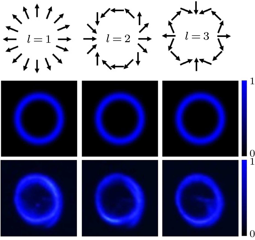
Fig. 2. Intensity and polarization distribution of generated ultraviolet PV beams with topological charges $l = 1,\, 2,\, 3$. The first row describes the polarization distribution. The second and third rows denote the simulation and experimental results, respectively.
To characterize the vectorial properties of the generated ultraviolet PV beams, we insert a GT prism between the filter F and the screen S. For simplicity, we set the initial phase $2 \gamma + \beta /2 + \eta /2 = 0$; thus, the generated ultraviolet PV beams can be simplified to $E_{\rm SF}({\rho,\phi})={4i\omega_{3}^{2} d_{\rm eff} L}/{({k_{3} c^{2}})\cdot } A_{1} A_{2} \delta({r-r_{\rm r} })e^{i({\beta / {2-\eta/2}})}{{\cos({l\phi})}\choose{\sin({l\phi})}} $. In this case, the first and third rows of Fig. 3 respectively describe the simulated intensity pattern of the generated ultraviolet PV beams with topological charges $l = 1,\, 2$ when the GT prism has different polarization angles (30$^{\circ}$, 60$^{\circ}$, 90$^{\circ}$, 120$^{\circ}$, 150$^{\circ}$) with respect to the horizontal direction. As the topological charge $l$ determines the polarization period per rotation, the number of lobes is equal to $2l$. As shown in the second and forth rows of Fig. 3, the PV beams experimentally split into two and four lobes, which match well with the cases of $l = 1,\, 2$, respectively. The two lobes are always recognizable with the extinction direction orthogonal to the polarization direction of the GT prism while the topological charge $l = 1$, as shown in Figs. 3(a1)–3(a5) and 3(b1)–3(b5). By contrast, for the topological charge $l = 2$, the intensity patterns behind the GT prism are distinguishable because of two orthogonal extinction directions, as shown in Figs. 3(c1)–3(c5) and 3(d1)–3(d5). The extinction direction rotates anticlockwise as the polarization angle of the GT prism increases. The experimental results basically coincide with the simulated ones. The defect may be attributed to the small deviation between the two FF beams.
cpl-39-3-034201-fig3.png
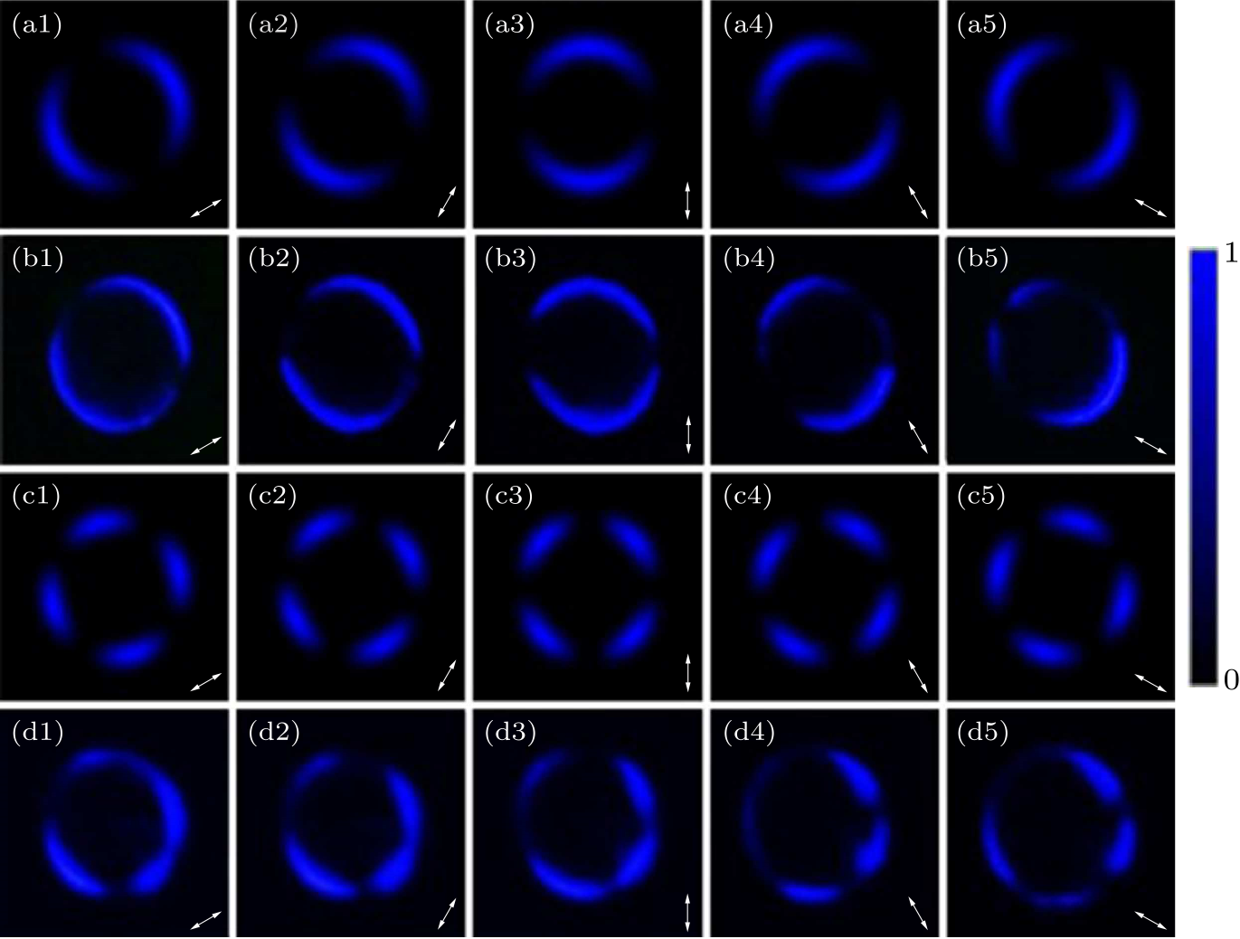
Fig. 3. (a1)–(a5) and (c1)–(c5) respectively represent the simulated intensity profiles of the ultraviolet PV beams with topological charges $l = 1,\, 2$ when the GT prism has different polarization angles (30$^{\circ}$, 60$^{\circ}$, 90$^{\circ}$, 120$^{\circ}$, 150$^{\circ}$) with respect to the horizontal direction. The corresponding experimental results are shown in (b1)–(b5) and (d1)–(d5). The arrows in the lower right corner of the figures show the polarization angles of the GT prism with respect to the horizontal direction.
cpl-39-3-034201-fig4.png
Fig. 4. Variation of the power of the generated ultraviolet PV beams with topological charge $l$.
Finally, we measure the intensity variation of the generated ultraviolet PV vector beams with the topological charges $l = 1,\, 2,\, 3,\, 4$. The power of the generated PV beams, as evident in Fig. 4, decreases from 40 µW for $l = 1$ to 15.5 µW for $l = 4$. Such a decrease in the power of the generated ultraviolet PV vector beams is due to the increase of the dark spot size of the Bessel vortex beam with different topological charges.[38] The demand for many applications to shift the frequency into the target one has increased recently. Unlike the linear method, nonlinear frequency conversion provides a fascinating and significant way to manipulate the polarization distribution of PV beams at a new frequency. It also allows us to transfer vectorial properties to another wavelength that is inaccessible, thereby opening up many interesting potential applications in microscopy imaging and optical communication. In conclusion, we experimentally and theoretically demonstrate the generation of PV beams in the ultraviolet regime driven by the nonlinear frequency conversion process. The results verify the properties of PV beams for invariant intensity and space-variant polarization distribution. Moreover, the relationship between topological charges and the power of PV beams is considered. We expect that the proposed method provides a simple way to generate PV beams in deep ultraviolet wavebands and shows potential applications to optical manipulation. Acknowledgments. This work was supported by the National Key Research and Development Program of China (Grant Nos. 2017YFA0303700 and 2018YFA0306301), the National Natural Science Foundation of China (Grant Nos. 11734011, 12004245, and 62105154), the Foundation for Shanghai Municipal Science and Technology Major Project (Grant No. 2019SHZDZX01-ZX06), the Shandong Quancheng Scholarship (Grant No. 00242019024), the China Postdoctoral Science Foundation (Grant No. 2021M691601), and the Natural Science Foundation of Jiangsu Province (Grant No. BK20210324).
References Revealing Local Field Structure of Focused Ultrashort PulsesCreation of a three-dimensional optical chain for controllable particle deliveryGeneration of a controllable optical cage by focusing a Laguerre–Gaussian correlated Schell-model beamTunable optical cage array generated by Dammann vector beamCreation and Detection of Vector Vortex Modes for Classical and Quantum CommunicationStorage and retrieval of vector beams of light in a multiple-degree-of-freedom quantum memoryOptical frequency conversion of light with maintaining polarization and orbital angular momentumGeneration of arbitrary vector beams with liquid crystal polarization converters and vector-photoaligned q-platesSynthesis of vector nonuniformly correlated light beams by a single digital mirror deviceGeneration of arbitrary vector vortex beams on hybrid-order Poincaré sphere based on liquid crystal deviceControlling optical field collapse by elliptical symmetry hybrid polarization structurePerfect Higher-Order Poincaré Sphere Beams from Digitalized Geometric PhasesNanoscale Polarization Manipulation and Encryption Based on Dielectric MetasurfacesNonlinear Vectorial Metasurface for Optical EncryptionVector Vortex Beam Generation with a Single Plasmonic MetasurfaceGeneration of Nondiffracting Vector Beams with Ring-Shaped Plasmonic MetasurfacesExperimental realization of scalar and vector perfect Laguerre–Gaussian beamsVectorial optical field generator for the creation of arbitrarily complex fieldsExtreme ultraviolet vector beams driven by infrared lasersAchromatic vector vortex beams from a glass coneUltralow-loss geometric phase and polarization shaping by ultrafast laser writing in silica glassTailoring of arbitrary optical vector beamsDigitalized Geometric Phases for Parallel Optical Spin and Orbital Angular Momentum EncodingGeometric phase from Aharonov–Bohm to Pancharatnam–Berry and beyondSpin-controlled massive channels of hybrid-order Poincaré sphere beamsGeneration of perfect vectorial vortex beamsSimultaneous generation of multiple perfect polarization vortices with selective spatial states in various diffraction ordersGeneration of arbitrary perfect Poincaré beamsGeneration of perfect vortex and vector beams based on Pancharatnam-Berry phase elementsDual waveband generator of perfect vector beamsSmart optically induced nonlinear photonic crystals for frequency conversion and controlBroadband generation of perfect Poincaré beams via dielectric spin-multiplexed metasurfaceHigh efficiency generation of tunable ellipse perfect vector beamsGeneration of elliptic perfect optical vortex and elliptic perfect vector beam by modulating the dynamic and geometric phaseSpatial-Polarization-Independent Parametric Up-Conversion of Vectorially Structured LightNonlinear frequency conversion and manipulation of vector beamsUltraviolet waveband vector beams generation assisted by the nonlinear frequency conversionFrequency-conversion of vector vortex beams with space-variant polarization in single-pass geometry
[1] Hnatovsky C, Shvedov V, Krolikowski W, and Rode A 2011 Phys. Rev. Lett. 106 123901
[2] Zhao Y, Zhan Q, Zhang Y, and Li Y P 2005 Opt. Lett. 30 848
[3] Chen Y and Cai Y 2014 Opt. Lett. 39 2549
[4] Weng X, Du L, Shi P, and Yuan X 2017 Opt. Express 25 9039
[5] Ndagano B, Nape I, Cox M A, Rosales-Guzman C, and Forbes A 2018 J. Lightwave Technol. 36 292
[6] Parigi V, D'Ambrosio V, Arnold C, Marrucci L, Sciarrino F, and Laurat J 2015 Nat. Commun. 6 7706
[7] Ren Z C, Lou Y C, Cheng Z M, Fan L, Ding J, Wang X L, and Wang H T 2021 Opt. Lett. 46 2300
[8] Chen P, Ji W, Wei B Y, Hu W, Chigrinov V, and Lu Y Q 2015 Appl. Phys. Lett. 107 241102
[9] Zhu X, Yu J, Wang F, Chen Y, Cai Y, and Korotkova O 2021 Opt. Lett. 46 2996
[10] Lou S, Zhou Y, Yuan Y, Lin T, Fan F, Wang X, Huang H, and Wen S 2019 Opt. Express 27 8596
[11] Wang D, Pan Y, Lü J Q, Li P P, Liu G G, Cai M Q, Li Y, Tu C, and Wang H T 2018 J. Opt. Soc. Am. B 35 2373
[12] Xu R, Chen P, Tang J, Duan W, Ge S J, Ma L L, Wu R, Hu W, and Lu Y Q 2018 Phys. Rev. Appl. 10 034061
[13] Zhao R, Huang L, Tang C, Li J, Li X, Wang Y, and Zentgraf T 2018 Adv. Opt. Mater. 6 1800490
[14] Tang Y, Intaravanne Y, Deng J, Li K F, Chen X, and Li G 2019 Phys. Rev. Appl. 12 024028
[15] Yue F, Wen D, Xin J, Gerardot B D, Li J, and Chen X 2016 ACS Photon. 3 1558
[16] Zhang Y, Yang X, and Gao J 2019 Phys. Rev. Appl. 11 064059
[17] Liu X, Monfared Y E, Pan R, Ma P, Cai Y, and Liang C 2021 Appl. Phys. Lett. 119 021105
[18] Han W, Yang Y, Cheng W, and Zhan Q 2013 Opt. Express 21 20692
[19] Hernández-García C, Turpin A, Román J S, Picón A, Drevinskas R, Cerkauskaite A, Kazansky P G, Durfee C G, and Sola Íñigo J 2017 Optica 4 520
[20] Radwell N, Hawley R D, Götte J B, and Franke-Arnold S 2016 Nat. Commun. 7 10564
[21] Sakakura M, Lei Y, Wang L, Yu Y H, and Kazansky P G 2020 Light: Sci. & Appl. 9 15
[22] Maurer C, Jesacher A, Fürhapter S, Bernet S, and Ritsch-Marte M 2007 New J. Phys. 9 78
[23] Chen P, Ge S J, Duan W, Wei B Y, Cui G X, Hu W, and Lu Y Q 2017 ACS Photon. 4 1333
[24] Cohen E, Larocque H, Bouchard F, Nejadsattari F, Gefen Y, and Karimi E 2019 Nat. Rev. Phys. 1 437
[25] Zhang Y H, Chen P, Ge S J, Wei T, Tang J, Hu W, and Lu Y Q 2020 Appl. Phys. Lett. 117 081101
[26] Li P, Zhang Y, Liu S, Ma C, Han L, Cheng H, and Zhao J 2016 Opt. Lett. 41 2205
[27] Fu S, Gao C, Wang T, Zhang S, and Zhai Y 2016 Opt. Lett. 41 5454
[28] Li D, Feng S, Nie S, Chang C, Ma J, and Yuan C 2019 J. Appl. Phys. 125 073105
[29] Liu Y, Ke Y, Zhou J, Liu Y, Luo H, Wen S, and Fan D 2017 Sci. Rep. 7 44096
[30] Li H, Liu H, and Chen X 2019 Photon. Res. 7 1340
[31] Liu D, Liu S, Mazur L, Wang B, Lu P, Krolikowski W, and Sheng Y 2020 Appl. Phys. Lett. 116 051104
[32] Liu M, Huo P, Zhu W, Zhang C, Zhang S, Song M, Zhang S, Zhou Q, Chen L, Lezec H J, Agrawal A, Lu Y, and Xu T 2021 Nat. Commun. 12 2230
[33] Li L, Chang C, Yuan C, Feng S, Nie S, Ren Z C, Wang H T, and Ding J 2018 Photon. Res. 6 1116
[34] Li D, Chang C, Nie S, Feng S, Ma J, and Yuan C 2018 Appl. Phys. Lett. 113 121101
[35] Wu H J, Zhao B, Rosales-Guzman C, Gao W, Shi B S, and Zhu Z Z 2020 Phys. Rev. Appl. 13 064041
[36] Liu H, Li H, Zheng Y, and Chen X 2018 Opt. Lett. 43 5981
[37] Li H, Liu H, Yang Y, Lu R, and Chen X 2021 Appl. Phys. Lett. 119 011104
[38] Saripalli R K, Ghosh A, Chaitanya N A, and Samanta G K 2019 Appl. Phys. Lett. 115 051101