Chinese Physics Letters, 2020, Vol. 37, No. 5, Article code 054202 Indium Tin Oxide Coated D-Shape Fiber as a Saturable Absorber for Generating a Dark Pulse Mode-Locked Laser * B. Nizamani1, S. Salam1,2, A. A. A. Jafry3, N. M. Zahir4, N. Jurami4,5, M. I. M. Abdul Khudus4, A. Shuhaimi5, E. Hanafi1, S. W. Harun1,6** Affiliations 1Photonics Engineering Laboratory, Department of Electrical Engineering, University of Malaya, 50603 Kuala Lumpur, Malaysia 2Faculty of Information Technology, Imam Ja'afar Al-Sadiq University, Baghdad, Iraq 3Department of Physics, Faculty of Science, Universiti Teknologi Malaysia, 81310 Skudai, Johor, Malaysia 4Department of Physics, Faculty of Science, University of Malaya, 50603 Kuala Lumpur, Malaysia 5Low-Dimensional Materials Research Center, Department of Physics, Faculty of Science, University of Malaya, 50603 Kuala Lumpur, Malaysia 6Department of Engineering, Faculty of Vocational Studies, Airlangga University, Surabaya, Indonesia Received 1 February 2020, online 25 April 2020 *Supported by the Ministry of Education of Malaysia (Grant No. LR001A-2016A) and University of Malaya (Grant No. RP039C-18AFR).
**Corresponding author. Email: swharun@um.edu.my
Citation Text: Nizamani B, Salam S, Jafry A A A, Zahir N M and Jurami N et al 2020 Chin. Phys. Lett. 37 054202    Abstract A dark pulse mode-locked laser is experimentally demonstrated using the indium tin oxide (ITO) coated D-shape fiber as a saturable absorber (SA). Using the polishing wheel technique, a D-shape single mode fiber was fabricated. A 60-nm-thick layer of ITO was deposited over the D-shape fiber using the electron beam deposition method. The SA has a saturation intensity of 40.32 MW/cm$^{2}$ and a modulation depth of 3.5%. A stable dark pulse mode-locked laser was observed at a central wavelength of 1559.4 nm with repetition rate 0.98 MHz, pulse width 370 ns and signal-to-noise ratio 61 dB. DOI:10.1088/0256-307X/37/5/054202 PACS:42.60.Da, 42.70.Hj, 42.60.-v © 2020 Chinese Physics Society Article Text Ultrafast lasers have drawn attention in the past two decades thanks to their many applications in optical communication, medical and material processing.[1–3] Pulsed fiber lasers can be generated by two techniques: active and passive. Active mode-locking can be achieved using modulator inside the cavity. However, this technique requires additional elements such as lenses and mirrors, which introduce more complexities and losses to the cavity. Meanwhile, passive mode-locked lasers are more advantageous owing to the simplicity, low cost and compactness.[4,5] Saturable absorbers (SAs) are one of the most efficient ways to generate passive mode-locking.[6,7] Several materials have been proposed in the literature, such as semiconductor saturable absorber mirrors (SESAMs), carbon nanotubes (CNTs) and graphene. Researchers have widely used SESAMs for passively generating mode-locked lasers.[8,9] However, SESAMs have narrow operational bandwidth due to high manufacturing cost and complex fabrication. Attention was then moved to CNTs because they can easily be fabricated at low cost. However, CNTs require charity control and bandgap engineering which limit its practical applications.[10–13] In contrast, graphene has several advantages in pulsed fiber lasers, including ultrafast recovery time, wide absorption spectrum, and low-cost fabrication process. However, graphene has the disadvantages of low absorption per layer and zero bandgap, which limit its practical application parameters. So far, a series of materials have been studied as SAs, including 2D nanomaterials such as topological insulators (TI), black phosphorus and transition metal dichalcogenides (TMDs).[14–18] However, there is still room to study novel materials to be used as SAs. In contrast to the study of bright pulses, the behavior of nonlinear systems can be classified into bright and dark pulsing operations, depending on nonlinear propagation of light through the system. While the dark pulses are theoretically and experimentally reported to have more advantages over the bright pulses, dark pulsing tends to be less sensitive to fiber loss and its pulse shape is less affected by noise as compared to the bright pulse.[19–21] Numerous studies have been demonstrated for the formation of dark pulses as the research attention is moving towards the trend of dark pulse generations rather than bright pulses.[21–24] However, few reports have addressed the use of indium tin oxide (ITO) to generate a dark pulse mode-locked laser. ITO has excellent nonlinear properties, whereby it can generate both the bright pulses and dark pulses depending on the cavity characteristics. The optical nonlinearities of ITO are studied at fast recovery time of nearly 360 fs with rise time lower than 200 fs, as reported in Ref. [25]. Optical Kerr nonlinearity in ITO has been reported in Ref. [26], which proved ITO to be an interesting material for ultrafast optics. Thus, in this work, we experimentally analyze the nonlinear behavior of ITO as SA by dark pulse formation using ITO over D-shape fiber via a strong evanescent field interaction. To the best of our knowledge, this is the first time that this technique has been used to develop dark pulse mode-locking operation. A D-shape fiber was prepared out of a single mode fiber (SMF-28) having core diameter of 9 µm and cladding diameter of 125 µm. Conventional side polishing technique was used for the fabrication as shown in Fig. 1(a). The setup first included adjustable polishing wheel polymerizing vinyl chloride (PVC) shaft and fiber holders were deployed beside it. In the region of interest, the fiber buffer was removed for about 3 mm and cleaned with alcohol to ensure that no buffer residues remain over the fiber. The fiber was then connected with amplified stimulated emission (ASE) as a light source and optical power meter (OPM) (Thorlabs:PM100D) to observe the power. The region of fiber with removed buffer and exposed cladding was placed over the polishing wheel with the help of pre-deployed fiber holders. The fiber holders ensured that the fiber was held firmly without giving any horizontal movement to fiber during the polishing process. A polishing wheel was covered with a 1000cw electro coated abrasive paper and was powered with 5 V DC supply with the adjustable speed using a manual knob. The traces of fiber over the abrasive paper during the side polishing process ensured that the partial cladding was removed and the variation in output power was monitored in real time. The process was completed until the insertion loss became 2 dB from the reference value. The fiber was then taken over the glass slide and its remaining thickness was measured with a Medilux-12 microscope. After multiple attempts of side polishing, it was observed that fiber thickness reduces to nearly 81.9 µm as shown in Fig. 1(b).
cpl-37-5-054202-fig1.png
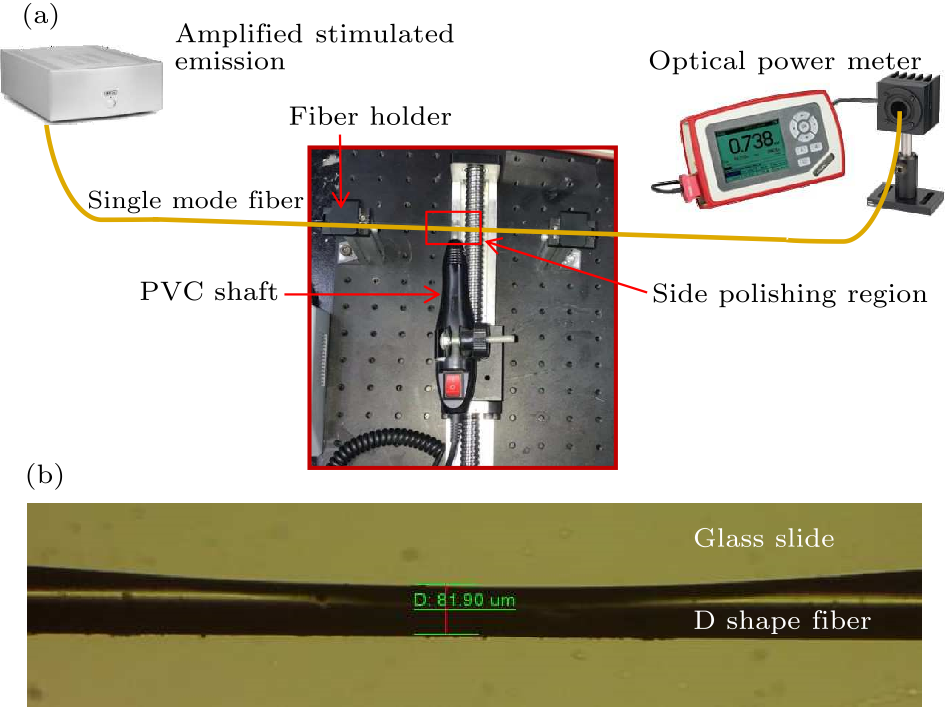
Fig. 1. (a) Fabrication setup of the D-shape fiber, and (b) the D-shape fiber.
Electron beam (e-beam) deposition can give precise deposition of the material up to 1000-nm thickness, which results in high density of film coating and strong adhesion with the substrate. It is also possible to deposit materials with a high melting point using e-beam deposition, such as ITO in this case. Thus, the fabricated D-shape fiber was then placed inside the e-beam chamber for ITO deposition, as shown in Fig. 2. The socket with the ITO target material was set to be used and the deposition process was initiated under the full vacuum condition of $9\times 10^{-6}$ Torr. Deposition of ITO was carried out from a 99.99% pure target material of In$_{2}$O$_{3}$/SnO$_{2}$ pieces at 90 and 10 wt%, respectively. After e-beam deposition process, the layer of ITO was deposited over the side polished region of fiber, as shown in a schematic diagram in Fig. 2. We selected e-beam deposition rather than other available techniques such as spin coating, rf magnetron sputtering and direct dropping of ITO,[27–30] as the other techniques involve additional elements with ITO and adhesion of ITO is not ensured in direct liquid dripping. In the current situation, ITO thickness was controlled and set to 60 nm.
cpl-37-5-054202-fig2.png
Fig. 2. Electron beam deposition for ITO coating over D-shape region.
cpl-37-5-054202-fig3.png
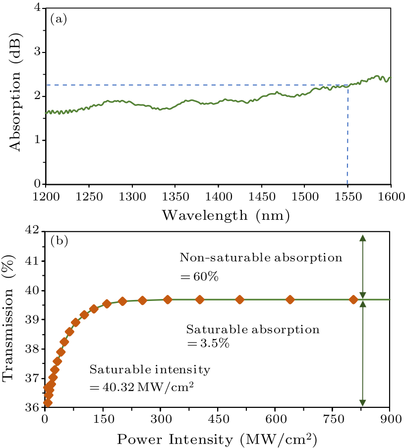
Fig. 3. Optical properties of ITO coated over the D-shape fiber: (a) linear absorption, (b) nonlinear absorption.
Linear absorption and nonlinear absorption of our SA having D-shape fiber coated with ITO are characterized in Fig. 3. As shown in Fig. 3(a), a 400 nm span was recorded with an optical spectrum analyzer (OSA) (Yokogawa:AQ6370B) having a resolution of 1 nm, within the wavelength range of 1200–1600 nm. At 1550 nm, about 2 dB spectral absorption was observed. Balance twin detector technique was used for the observation of nonlinear absorption characteristic of D-shape fiber coated with ITO. Transmission of D-shape fiber coated with ITO was obtained with variation in pump power as shown in Fig. 3(b). A stable mode-locked laser pulse is used as a source with operating wavelength of 1557.7 nm. The pulse width and repetition rate of mode-locked source were 3.6 ps and 1.89 MHz, respectively. The picosecond laser was launched into the D-shape fiber, so that it interacted with the coated ITO layer on the polished surface to measure the nonlinear absorption. The transmission data was fitted based on Eq. (1), whereas the red diamonds in Fig. 3(b) represent the experimental data and the green line denotes the fitting data. With the increase in pump power, the transmission increased rapidly and then saturated gradually. In Eq. (1), $T(I)$ denotes the transmission, $\Delta T$ represents modulation depth, $T_{\rm ns}$ denotes non-saturable absorption, while $I_{\rm sat}$ and $I$ represent saturable intensity and input intensity, respectively. The saturation intensity was calculated to be 40.32 MW/cm$^{2}$, modulation depth and non-saturable absorption were measured to be 3.5% and 60%, respectively. This result indicates that ITO coated over a D-shape fiber had good nonlinear behavior, and thus it is a suitable candidate for SA. However, the SA has a large non-saturable absorption, which may increase the pulse width. The non-saturable absorption can be reduced by increasing the D-shape length, which would allow the longer deposition region of ITO and increasing the thickness of D-shape region to avoid the losses. $$ T\left(I \right)=1-\Delta T \cdot \exp \left({{-I}/{I_{\rm sat}} } \right)-T_{\rm ns}.~~ \tag {1} $$
cpl-37-5-054202-fig4.png
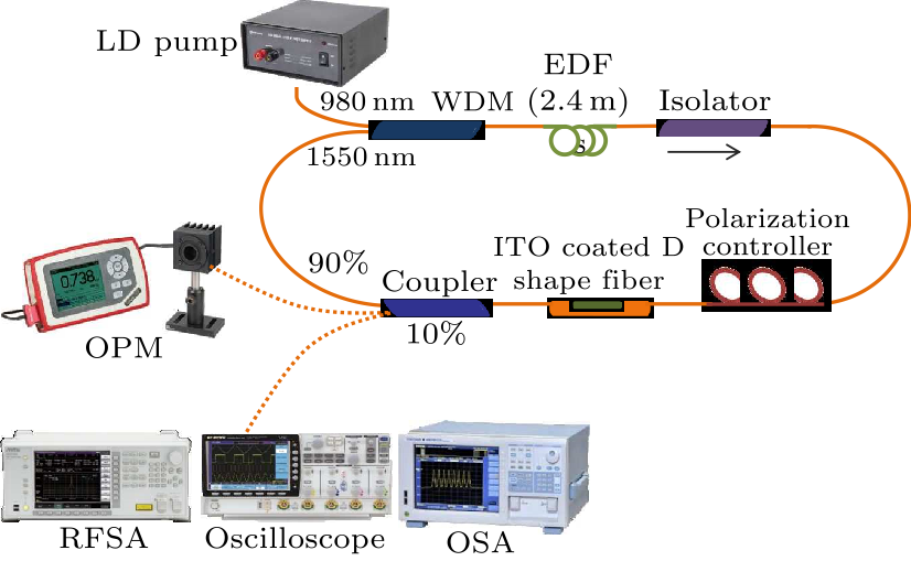
Fig. 4. EDFL ring cavity setup.
As shown in Fig. 4, a laser diode (LD) pump was connected to the 980 nm port of 980 nm/1550 nm wavelength division multiplexer (WDM) as a laser source. Output from WDM was connected to an erbium-doped fiber (EDF) used as a gain medium. EDF had a length of 2.4 m, numerical aperture of 0.23, absorption coefficient of 25 dB/m at 980 nm, core diameter of 4 µm and cladding diameter of 125 µm. EDF was then connected to a polarization-independent isolator to force unidirectional clockwise propagation of light inside the cavity. At the other end, the isolator was connected to a 3-loop mechanical polarization controller (PC) (Phoenix photonics). A PC was then connected to SA which was an ITO coated D-shape fiber. After the SA, a coupler with the output of 90/10 was connected to split the output power in the portion of 90% and 10%. One output end of coupler generating 90% of power was connected back to the 1550 nm port of WDM, to oscillate the light inside cavity. The other end of coupler providing 10% of power was connected to an oscilloscope (GWINSTEK:GDS-3352) for the time domain pulse train, OPM (Thorlabs:PM100D) for the measurement of the output power of cavity, OSA (Yokogawa:AQ6370B) at the resolution of 0.07 nm for wavelength analyses and radio frequency spectrum analyzer (RFSA) (Anritsu:MS2683 A) having operating range between 9 kHz to 7.8 GHz to observe the frequency spectrum. However, the connectivity to RFSA and the oscilloscope was performed through the fast-photo-detector (Thorlabs:DET10D/M). Total cavity length was measured to be 214 m.
cpl-37-5-054202-fig5.png
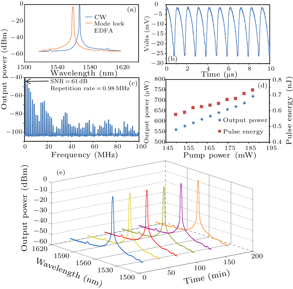
Fig. 5. Experimental results: (a) operating wavelength spectrum of continuous wave and mode locked, (b) oscilloscope trace ensuring dark pulse, (c) frequency spectrum, (d) output power and pulse energy against pump power, (e) mode locked laser stability for three hours.
The aim of this work was to achieve ultrafast lasers with the smallest possible layer of ITO to be coated over a D-shape fiber. Taking advantage of having controlled deposition of ITO thickness through e-beam, we deposited ITO with thickness of 40 nm, 50 nm and 60 nm. Because no pulsed operation was obtained with the ITO thickness of 40 nm and 50 nm, we selected 60-nm-thick ITO for our work to achieve pulsed lasing. The length of the ITO layer deposited over the D-shape fiber was the length of the side polished region, which was measured to be about 1.02 mm. Before insertion of SA to the cavity, we confirmed that our erbium-doped fiber laser (EDFL) cavity could generate continuous-wave (CW) lasing at the central wavelength of 1567 nm. With CW lasing, the threshold pump power was 30.3 mW as shown in Fig. 5(a). Then we successfully generated mode-locked lasing by inserting our D-shape fiber coated with ITO. The mode-locking operational wavelength was recorded to be 1559 nm, while it was stable in the pump power range 150–187 mW. Figure 5(a) shows the shift of spectrum from CW at 1567 nm to pulsed laser at an operational wavelength of 1559 nm. The operating wavelength shifted to a shorter wavelength, which has a larger gain to compensate for the loss induced by the insertion of the SA device. The threshold pump power for the mode-locking operation is also relatively high due to the insertion loss. However, cavity length optimization could result in lower pump power operation of the mode-locked laser. Figure 5(b) illustrates the time domain pulse train obtained through the oscilloscope at the pump power of 187 mW within the span of 10 µs time. We generated dark pulses by adjusting PC inside cavity to optimize birefringence and taking advantage of nonlinear behavior of ITO. The uniform amplitude of pulse train and pulse period indicated that the mode-locked operation was stable. At the pump power of 187 mW, pulse width of the dark pulse was measured to be 370 ns with the repetition rate of 972.8 kHz, pulse-to-pulse interval was obtained to be 1028 ns. The long width of the pulse could be related to large non-saturable absorption as well as to long relaxation process of as-growth ITO. Pump power was increased from 187 mW to maximum sustainable power of the LD, which was 207 mW. By increasing pump power from 187 mW to 207 mW, the mode-locked pulse disappeared beyond 187 mW and CW laser state was retained. Mode-locked pulse operation was retained back when the pump power was reduced from 207 mW to 187 mW. This operation was stable until further decrease of pump power to 150 mW. We observed that SA was not burnt and lasing was achieved when pump power was reduced back to 187 mW. Our observation concludes that the SA damage threshold is beyond the operating limits of our LD, which is 207 mW. Figure 5(c) shows the radio frequency spectrum recorded within the range of 100 MHz. The spectrum gave more than 50 peaks showing the stability of mode-locked operation. Desirable quality of signal-to-noise ratio (SNR) was measured to be 61 dB for the fundamental frequency. High SNR and numerous harmonics indicate stable mode-locked operation. These results are comparable to the previous study reported by Guo et al.[27] However, stability is not justified in previous work,[27] while our proposed technique of having strong evanescent field interaction with ITO improves stability of the dark pulse, which is proven by the observation of much higher SNR of fundamental frequency. E-beam deposition also provides a strong adhesion of ITO onto the polished surface, which enhances the robustness of the laser rather than liquid dripping of ITO. Relationship of pump power against output power and pulse energy is plotted in Fig. 5(d). Output power was observed to increase linearly from 560 µW to 720 µW and pulse energy also increased linearly from 0.575 nJ to 0.73 nJ with the increase of pump power within the range of 150–187 mW. The stability was further confirmed by recording the spectrum at interval of every 30 min for 180 min. Figure 5(e) shows that the spectrum was stable in terms of wavelength and power for three hours. The central wavelength gave no obvious change while peak amplitudes varied within $\pm$0.6 dB. It is also observed that the proposed mode-locked laser operated stably in the laboratory condition by maintaining its high SNR, pulse wavelength and pulse width for at least 48 hours without any noticeable degradation of performance. It is worth noting that the dark pulses could not be obtained after the removal of our SA even if we adjust the PC or vary the pump power to all possible values. To the best of our knowledge, coating of ITO over the D-shape fiber was responsible for generation of dark pulses. In conclusion, we have successfully demonstrated dark pulse generation through a mode-locking operation using an ITO coated D-shape fiber as an SA in an EDFL cavity. Strong adhesion of ITO was ensured by e-beam deposition process. Taking advantage of strong adhesion and nonlinear properties of ITO, we managed to generate dark pulses that are less sensitive to fiber loss as compared to bright pulses. The mode-locked operational wavelength was recorded to be 1559 nm, with the repetition rate of 972.8 kHz and pulse width of 370 ns. The pulses generated were excellent as the constructed laser configuration exhibited an SNR of approximately 61 dB at the maximum attainable pump power of 187 mW. The deposition of ITO onto the D-shape fiber demonstrated strong light-matter coupling, which will eventually generate dark pulse mode-locked with comparable laser parameters to other approaches, including thin-film and optical deposition of SA.
References Recent developments in compact ultrafast lasersDistributed ultrafast fibre laserUltrafast lasers—reliable tools for advanced materials processingMicrofiber-based WS_2-film saturable absorber for ultra-fast photonicsGraphene Oxide vs Reduced Graphene Oxide as saturable absorbers for Er-doped passively mode-locked fiber laserTris-(8-hydroxyquinoline) aluminium thin film as saturable absorber for passively Q-switched erbium-doped fibre laserFIrpic thin film as saturable absorber for passively Q-switched and mode-locked erbium-doped fiber laserPicosecond SESAM-Based Ytterbium Mode-Locked Fiber LasersSemiconductor saturable absorber mirrors (SESAM's) for femtosecond to nanosecond pulse generation in solid-state lasersAtomic-Layer Graphene as a Saturable Absorber for Ultrafast Pulsed LasersVersatile multi-wavelength ultrafast fiber laser mode-locked by carbon nanotubesLow threshold linear cavity mode-locked fiber laser using microfiber-based carbon nanotube saturable absorberShort pulse fiber lasers mode-locked by carbon nanotubes and grapheneA practical topological insulator saturable absorber for mode-locked fiber laserMolybdenum disulfide (MoS_2) as a broadband saturable absorber for ultra-fast photonicsQ-Switched Ytterbium-Doped Fiber Laser Using Black Phosphorus as Saturable AbsorberGeneration of passively Q-switched fiber laser at 1 μm by using MoSSe as a saturable absorberPassively mode-locked erbium-doped fiber laser via a D-shape-fiber-based MoS 2 saturable absorber with a very low nonsaturable lossPropagation properties of dark solitonsHarmonic mode locking counterparts of dark pulse and dark-bright pulse pairsDark solitons in WS_2 erbium-doped fiber lasersDark pulse generation in fiber lasers incorporating carbon nanotubesBlack phosphorus-enabled harmonic mode locking of dark pulses in a Yb-doped fiber laserCoexistence and evolution of bright pulses and dark solitons in a fiber laserLarge optical nonlinearity of indium tin oxide in its epsilon-near-zero regionCarrier concentration dependence of optical Kerr nonlinearity in indium tin oxide filmsDark solitons in erbium-doped fiber lasers based on indium tin oxide as saturable absorbersEffect of heat treatment atmosphere on the piezoresistivity of indium tin oxide ceramic strain sensorProperties of R.F. magnetron sputtered cadmium–tin–oxide and indium–tin–oxide thin filmsCharacterization of indium tin oxide (ITO) thin films prepared by a sol–gel spin coating process
[1] Keller U 2003 Nature 424 831
[2] Liu X et al 2015 Sci. Rep. 5 9101
[3] Sugioka K and Cheng Y 2014 Light: Sci. & Appl. 3 e149
[4] Yan P et al 2015 Opt. Mater. Express 5 479
[5] Sobon G et al 2012 Opt. Express 20 19463
[6] Salam S et al 2019 IET Optoelectron. 13 247
[7] Salam S et al 2019 Opt. Fiber Technol. 50 256
[8] Gomes L A, Orsila L, Jouhti T and Okhotnikov O G 2004 IEEE J. Sel. Top. Quantum Electron. 10 129
[9] Keller U et al 1996 IEEE J. Sel. Top. Quantum Electron. 2 435
[10] Bao Q et al 2009 Adv. Funct. Mater. 19 3077
[11] Liu X et al 2013 Sci. Rep. 3 2718
[12] Lau K et al 2018 Opt. Laser Technol. 102 240
[13] Yamashita S, Martinez A and Xu B 2014 Opt. Fiber Technol. 20 702
[14] Yan P, Lin R, Ruan S, Liu A, Chen H, Zheng Y, Chen S, Guo C and Hu J 2015 Sci. Rep. 5 8690
[15] Zhang H, Lu S, Zheng J, Du J, Wen S, Tang D and Loh K 2014 Opt. Express 22 7249
[16] Al-Masoodi A, Ahmed M, Latiff A, Arof H and Harun S W 2016 Chin. Phys. Lett. 33 054206
[17] Ahmad H, Reduan S, Aidit S and Tiu Z 2017 Chin. Opt. Lett. 15 020601
[18] Duan L N, Su Y L, Wang Y G, Li L, Wang X and Wang Y S 2016 Chin. Phys. B 25 024206
[19] Zhao W and Bourkoff E 1989 Opt. Lett. 14 703
[20] Li X, Zhang S, Meng Y and Hao Y 2013 Opt. Express 21 8409
[21] Liu W, Pang L, Han H, Shen Z, Lei M, Teng H and Wei Z 2016 Photon. Res. 4 111
[22] Liu H and Chow K 2014 Opt. Express 22 29708
[23] Wang T, Zhang W, Shi X, Wang J, Ding X, Zhang K, Peng J, Wu J and Zhou P 2019 Laser Phys. Lett. 16 085102
[24] Wang L 2013 Opt. Commun. 297 129
[25] Alam M Z, De Leon I and Boyd R W 2016 Science 352 795
[26] Elim H I, Ji W and Zhu F 2006 Appl. Phys. B 82 439
[27] Guo J, Zhang H, Li Z, Sheng Y, Guo Q, Han X, Liu Y, Man B, Ning T and Jiang S 2018 Opt. Mater. 78 432
[28] Yang S, Zhang C, Chang X, Huang J, Yang Z, Yao J, Wang H and Ding G 2019 Ceram. Int. 45 17048
[29] Wohlmuth W and Adesida I 2005 Thin Solid Films 479 223
[30] Cho H and Yun Y H 2011 Ceram. Int. 37 615