Chinese Physics Letters, 2017, Vol. 34, No. 9, Article code 090302Express Letter Space-to-Ground Quantum Key Distribution Using a Small-Sized Payload on Tiangong-2 Space Lab * Sheng-Kai Liao(廖胜凯)1,2†, Jin Lin(林金)1,2†, Ji-Gang Ren(任继刚)1,2, Wei-Yue Liu(刘尉悦)1,2, Jia Qiang(强佳)3, Juan Yin(印娟)1,2, Yang Li(李杨)1,2, Qi Shen(沈奇)1,2, Liang Zhang(张亮)2,3, Xue-Feng Liang(梁学锋)4, Hai-Lin Yong(雍海林)1,2, Feng-Zhi Li(李凤芝)1,2, Ya-Yun Yin(印亚云)1,2, Yuan Cao(曹原)1,2, Wen-Qi Cai(蔡文奇)1,2, Wen-Zhuo Zhang(张文卓)1,2, Jian-Jun Jia(贾建军)3, Jin-Cai Wu(吴金才)3, Xiao-Wen Chen(陈小文)3, Shan-Cong Zhang(张善从)4, Xiao-Jun Jiang(姜晓军)5, Jian-Feng Wang(王建峰)5, Yong-Mei Huang(黄永梅)6, Qiang Wang(王强)6, Lu Ma(马路)7, Li Li(李力)1,2, Ge-Sheng Pan(潘阁生)1,2, Qiang Zhang(张强)1,2, Yu-Ao Chen(陈宇翱)1,2, Chao-Yang Lu(陆朝阳)1,2, Nai-Le Liu(刘乃乐)1,2, Xiongfeng Ma(马雄峰)2, Rong Shu(舒嵘)2,3, Cheng-Zhi Peng(彭承志)1,2**, Jian-Yu Wang(王建宇)2,3**, Jian-Wei Pan(潘建伟)1,2** Affiliations 1Department of Modern Physics and Hefei National Laboratory for Physical Sciences at the Microscale, University of Science and Technology of China, Hefei 230026 2Shanghai Branch, CAS Center for Excellence and Synergetic Innovation Center in Quantum Information and Quantum Physics, Shanghai 201315 3Key Laboratory of Space Active Opto-Electronic Technology, Shanghai Institute of Technical Physics, Chinese Academy of Sciences, Shanghai 200083 4Beijing UCAS Space Technology Co., Ltd, Beijing 100190 5National Astronomical Observatories, Chinese Academy of Sciences, Beijing 100012 6Key Laboratory of Optical engineering, Institute of Optics and Electronics, Chinese Academy of Sciences, Chengdu 610209 7Xinjiang Astronomical Observatory, Chinese Academy of Sciences, Urumqi 830011 Received 8 August 2017 *Supported by China Manned Space Program, Technology and Engineering Center for Space Utilization Chinese Academy of Sciences, Chinese Academy of Sciences, and the National Natural Science Foundation of China.
These two authors contributed equally to this work.
**Corresponding author. Email: pcz@ustc.edu.cn; jywang@mail.sitp.ac.cn; pan@ustc.edu.cn
Citation Text: Liao S K, Lin J, Ren J G, Liu W Y and Qiang J et al 2017 Chin. Phys. Lett. 34 090302 Abstract Quantum technology establishes a foundation for secure communication via quantum key distribution (QKD). In the last two decades, the rapid development of QKD makes a global quantum communication network feasible. In order to construct this network, it is economical to consider small-sized and low-cost QKD payloads, which can be assembled on satellites with different sizes, such as space stations. Here we report an experimental demonstration of space-to-ground QKD using a small-sized payload, from Tiangong-2 space lab to Nanshan ground station. The 57.9-kg payload integrates a tracking system, a QKD transmitter along with modules for synchronization, and a laser communication transmitter. In the space lab, a 50 MHz vacuum + weak decoy-state optical source is sent through a reflective telescope with an aperture of 200 mm. On the ground station, a telescope with an aperture of 1200 mm collects the signal photons. A stable and high-transmittance communication channel is set up with a high-precision bidirectional tracking system, a polarization compensation module, and a synchronization system. When the quantum link is successfully established, we obtain a key rate over 100 bps with a communication distance up to 719 km. Together with our recent development of QKD in daylight, the present demonstration paves the way towards a practical satellite-constellation-based global quantum secure network with small-sized QKD payloads. DOI:10.1088/0256-307X/34/9/090302 PACS:03.67.Dd, 03.67.Hk, 42.50.Dv, 42.50.Ex © 2017 Chinese Physics Society Article Text Secure key distribution is one of the fundamental tasks in information science and technology. For example, the one-time pad encryption,[1] whose security is proven by Shannon,[2] requires an efficient way of secure key distribution. The principles of quantum mechanics can make two remote users, Alice and Bob, share identical private keys. Since the first quantum key distribution (QKD) protocol, the Bennett-Brassard-1984 (BB84)[3] protocol, tremendous developments have been made to bring the theory to reality. The ultimate goal is to establish a global quantum network or a secure quantum wide-area network. The first QKD experiment was implemented in 1989 with a communication distance of 32 cm.[4] Then the distance is extended to kilometers,[5] dozens of kilometers,[6] and up to 100 km[7,8] in free space, and up to several hundreds of kilometers[9-13] in fiber. Meanwhile, urban quantum networks have been demonstrated in telecom network around the world.[14-16] For both fiber and free space channels, practical QKD faces a key challenge that quantum signals cannot be amplified. This restricts the transmission distance of the scheme due to the increasing level of the attenuation and noise. For instance, with a 10 GHz perfect single-photon source and prefect detectors, it takes 300 years to transmit one bit for a distance of 1000 km in the standard telecom fiber. To realize long distance quantum communication for a global quantum network, two promising methods have been proposed to relay signals: one is the quantum repeater scheme[17] and the other is the satellite scheme.[18] The repeater scheme requires high-performance quantum memory devices, which are not available with the current technology. The satellite-based scheme is much more practical due to the advantage of little attenuation of light in space, where photons can travel from satellites to ground stations through thousands of kilometers. Moreover, the satellite can share keys with different ground stations globally due to the orbital motion. In recent years, great efforts have been made to test the feasibility of the satellite-to-ground QKD, including moving platforms[8,19] and long-distance free space channel on the ground.[7,8] The quantum science experiment satellite Micius was launched on 16th August 2016. After several months' testing and experiment, satellite-based entanglement distribution over 1200 kilometers,[20] satellite-to-ground QKD[21] and ground-to-satellite quantum teleportation[22] have been demonstrated. These results pave the way to global-scale quantum networks and space-scale quantum experiments.
cpl-34-9-090302-fig1.png
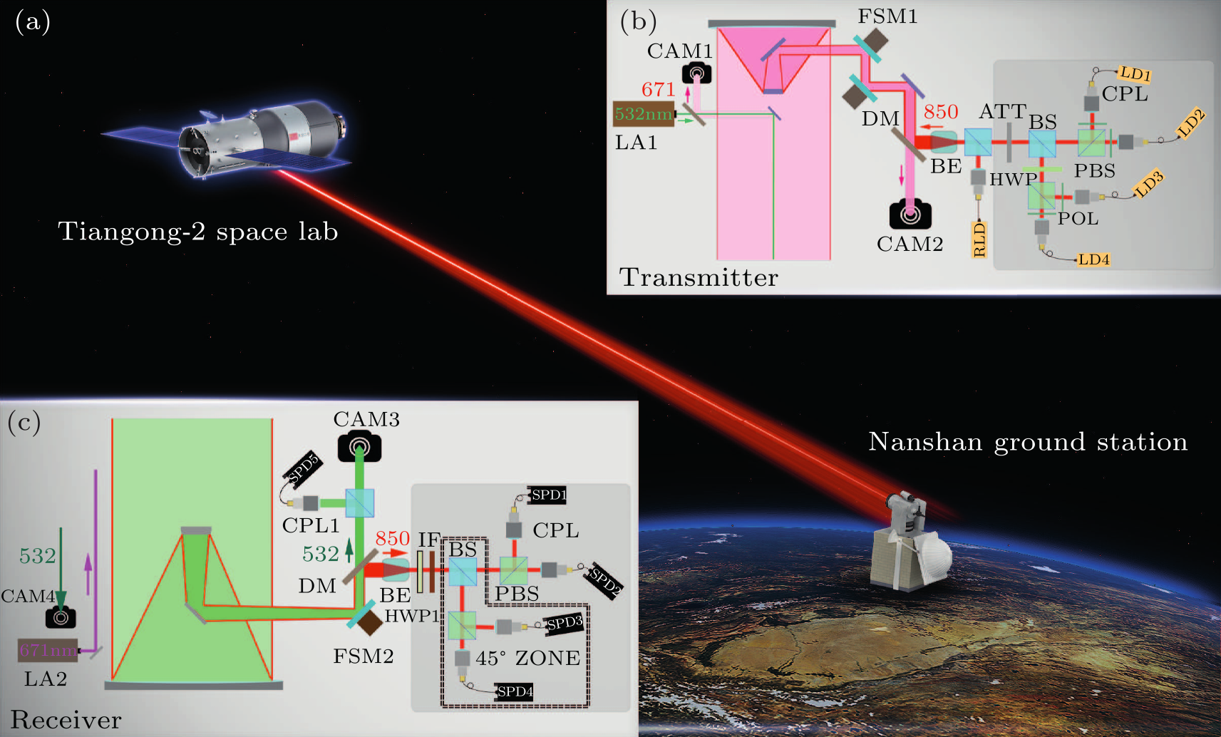
Fig. 1. Schematic diagram of the experimental setup. (a) Overview of the space-to-ground QKD. (b) Schematic of the decoy-state QKD transmitter. (c) Schematic of the decoy-state QKD decoder in the Nanshan ground station equipped with a 1200-mm-aperture telescope. LA1: green laser (532 nm), CAM1: coarse camera, CAM2: fine camera, LD: laser diode, RLD: reference laser diode, FSM1: fast steering mirror, HWP: half-wave plate, POL: polarizer, PBS: polarization beam splitter, BS: beam splitter, ATT: attenuation, LA2: red laser (671 nm), CAM3: fine camera, CAM4, coarse camera, CPL: coupler, DM: dichroic mirror, IF: interference filter, FSM2: fast steering mirror, BE: beam expander, SPD: single photon detector.
On the other hand, small-sized payloads for QKD, which can be assembled on either small satellites or big satellites such as space stations, can reduce the cost to construct a satellite constellation. Therefore, demonstrating the feasibility of QKD using small-sized and low-cost payloads is an important task. In this Letter, we report a space-to-ground QKD experiment using a small payload between the Tiangong-2 space lab and the Nanshan ground station (43$^{\circ}$28$'$31.66$''$N, 87$^{\circ}$10$'$36$''$E). The payload is 57.9 kg weight and integrates a tracking system, a QKD transmitter along with modules for synchronization, and a laser communication transmitter. The scheme is illustrated in Fig. 1. The transmitter (Alice) is put in the Tiangong-2 space lab and the receiver (Bob) is put in the Nanshan ground station. The BB84 QKD protocol is implemented with the vacuum + weak decoy-state scheme.[23,24] The experimental system includes a high-speed decoy-state source, a low beam diffraction optical system, a high-precision bidirectional tracking system, a polarization compensation module, and a synchronization system. In the experiment, the communication distance is within the range between 388 km and 719 km, the quantum bit error rate (QBER) is 1.8$\%$ and the final key rate is about 91 bps when the quantum channel is established. A schematic diagram of the transmitter in the space lab is shown in Fig. 1(b). Based on the decoy-state BB84 protocol, the source is made up with four vertical cavity surface emitting lasers and a BB84 encoding module. Photons are sent through a 200 mm diameter telescope to get a narrow divergence angle. A green laser beam which has a wavelength 532 nm, a power of 160 mW, a divergence angle of 1.25 mrad, a pulse full width at half maximum of 1.4 ns, and a repetition rate around 10 kHz, is coaxial with the telescope for system tracking and synchronization. In addition, there is a reference laser used for monitoring the channel depolarization. The quantum source emits vacuum decoy states, weak decoy states, and signal states for the vacuum + weak decoy-state BB84 scheme. The average photon number of the weak decoy state is $\nu=0.35$, and that of the signal state is $\mu=0.6$. Each of the decoy/signal state is randomly prepared in one of the four BB84 states, $| H \rangle$, $| V\rangle$, $|+\rangle$ and $|-\rangle$, where $| H \rangle $ and $| V\rangle$ represent the horizontal and vertical polarizations, respectively, and $|\pm\rangle=(| H\rangle\pm |V\rangle)/\sqrt{2}$ represent diagonal polarizations. Four fiber-coupled laser diodes with a wavelength of 850.15 nm, a repetition rate of 50 MHz, and a full width at half maximum of around 500 ps, are employed to emit photons in four paths for the BB84 encoding. The encoding module includes a half-wave plate (HWP), a beam splitter (BS), and two polarization beam splitters (PBSs). After encoding, a passive attenuator is employed to set the average photon number per pulse to the designed quantum level when the pulses leave the transmitter telescope. The intensity of each laser diode is randomly modulated to prepare the signal states, weak decoy states, and vacuum decoy states, whose ratio is set to 2:1:1. The random numbers used for state preparation are generated beforehand by a random physical noise chip. From the security point of view, it is critical to make photons indistinguishable from the four lasers in both of the spectrum and the temporal domains. The wavelengths of the laser diodes are carefully tuned to 850.15 nm by separate temperature controllers. The centers of the optical pulses are precisely controlled by adjusting the length of the driver's cable. The output beam is carefully aligned to the polarization encoding module with collimators to obtain both concentricity and coaxiality. In the space-to-ground QKD experiment, the light sent from the space lab is at the single-photon level and needs to travel for hundreds of kilometers to reach the ground station. Therefore, the link transmission efficiency becomes critical. The geometric loss dominans the total attenuation. Since the link transmittance is inversely proportional to the square of the product of the beam divergence and the travel distance, it is important to narrow the QKD light beam. In the transmitter, we use a reflective telescope with an aperture of 200 mm to narrow the beam divergence down to $\sim$35 μrad. The beam diameter is around 24.5 m after transmitting through 700 km free space. When a 1.2 m aperture telescope is used to collect the light, the corresponding geometric loss is about 27 dB. The setup on the receiver's side is presented in Fig. 1(c). A Ritchey–Chretien telescope with aperture of 1.2 m and a focal length of around 10 m is used to collect the QKD photons. The received photons first go through a motorized HWP for dynamical polarization compensation, and an interference filter for suppressing background noises, then they are sent to the BB84 decoding module with four single-photon detectors. The output electrical signals from the detectors are fed into a data acquisition computer with a time to digital convertor (TDC). The acquired data is stored in a harddisk for further processing. Meanwhile, a 671 nm continuous-wave red laser with a power of 2.2 W and a divergence angle of 1.2 mrad is sent from the ground station to the space lab for system tracking. The relative rotation between the transmitter and the receiver effectively introduces a rotation of the photon polarization. Since the QKD setup uses polarization encoding, such rotation needs to be compensated for. We first evaluate the rotation angle by taking account of the relative rotations and all birefringent elements in the optical link, then we use a motorized HWP for the dynamical compensation. As the Tiangong-2 space lab circles the earth with a speed of about 7.7 km/s and the beam divergence is only 35 $\mu$rad, a high-precision acquisition, tracking and pointing (ATP) system[25] becomes an essential component to establish the link between the space lab and the ground station. Both the transmitter and the receiver have a two-stage ATP system, which has a coarse tracking loop and a fine tracking loop. The coarse tracking loop includes a two-axis gimbal and a camera with wide field-of-view and low frame rate. In the transmitter, a complementary metal oxide semiconductor (CMOS) camera is used and in the receiver a charge-coupled device (CCD) camera is used. The fine tracking loop includes a fast steering mirror (FSM) and a camera with narrow field-of-view and high frame rate. In the transmitter, a CMOS camera is used and in the receiver a CCD camera is used. In the ATP system, first the receiver sends the 671 nm beacon laser to the transmitter. The transmitter captures the beacon laser with the coarse CMOS camera. Then the two-axis gimbal corrects its pointing direction according to the position of the light spot in the coarse camera, and guides the beacon laser into the fine CMOS camera. The FSM corrects its pointing direction according to the position of the light spot in the fine camera. The final tracking precision is about 1–2 μrad during the experiment. In order to further increase the pointing precision from the ground station to the space lab, the transmitter points the 532 nm beacon laser to the receiver. On the ground station, a beam splitter divides the received 532 nm light into two parts for tracking and synchronization, respectively. One part is used to guide the light into the detectors with a precision of 1–2 μrad. Then the stable optical link is established and remains locked in the closed-loop tracking. Note that the transmitter sends the QKD photons with a so-called point ahead angle, which is to compensate for the relative motion of the two terminals. The other part of the 532 nm light is used for synchronization. The transmitter in the space lab sends 50 MHz light pulses as quantum signals to the receiver while most of these signals are lost in the channel. The timing of the detected signals on the receiver side needs to match the pulse indexes of the corresponding encoded signals on the transmitter side. Since the transmitter and the receiver are separated far away and have independent reference clocks, a high-precision synchronization is needed. The synchronization is also used to distinguish the QKD signal photons from background noises. In the space lab, a small part of the 532 nm laser beam is used for synchronization, along with the Global Positioning System (GPS). The light is guided into a fast photodiode to be converted into electrical pulse signals. Meanwhile, a GPS receiver in the space lab emits pulse-per-second (PPS) signals. Both the pulse signals and the GPS PPS signals are fed into a TDC module of the transmitter. The TDC module uses the common clock with the QKD source encoding module. On the ground station, a part of the received 532 nm beacon is sent to a single-photon detector. The detection results, together with the GPS PPS signals, are used for the time reference of the quantum signal detections. As a result, the time jitter of the reference reaches 0.95 ns, which is used to tag the QKD detection events within a 2 ns time window in order to filter out background noises.
Table 1. Experimental procedures in different locations of the space lab and rough operation time.
Zenith angle Main procedure Time
of a typical pass
Beneath horizon System initialization
Horizon to $65^\circ$ Orientation initialization $\sim$200 s
$65^\circ$ to $60^\circ$ ATP $\sim$15 s
$65^\circ$ to $55^\circ$ Stable quantum link settlement $\sim$27 s
$55^\circ$ to $-65^\circ$ Quantum communication $\sim$130 s
Beneath $-65^\circ$ Data processing
The experimental procedures are listed in Table 1. The QKD link can be established only under the following conditions: (1) good weather and clear visibility; (2) the space lab and the ground station are in the shadow of the earth, that is, the experiment operates at night; (3) the duration when the transmitter on the space lab and the ground station can see each other is more than 60 s. When the space lab comes out from the horizon, the receiver telescope is pointed to a predicted orbital position. Then the receiver turns on the beacon laser to cover the predicted area. The telescope in the space lab is also pointed to the ground station with a predicted direction. Once the transmitter captures the beacon laser from the ground station with the coarse camera, they start the ATP and establish a quantum link.
cpl-34-9-090302-fig2.png
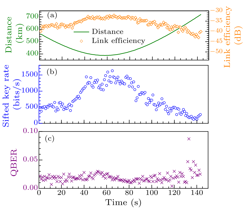
Fig. 2. Experimental results for one pass of space lab. (a) The distance of the space lab and the ground station and the link efficiency as a function of time. (b) The sifted key rate as a function of time. (c) Observed quantum bit error rate as a function of time.
On a typical orbit pass after the quantum link is established, the overall transmittance is nearly from $-32$ dB to $-42$ dB at the distance from 388 km to 719 km, which mainly includes the 21–26 dB geometric loss, the $-7$ dB optical efficiency on the receiver side. On the detection side, the background count rate is around 300 cps, including the dark count rate of the four single-photon detectors. The signal count rate is around 1000–5000 cps. With the time filtering of 2 ns, we achieve a mean sifted key rate of 783 bps in 143 s and a QBER of 1.8%. In total, we obtain 112031 bits sifted key of signal. When the space lab passes over the ground station, the optical link distance and the channel transmittance vary with time, then the sifted key rate and the QBER change over time as well. We show the experimental results for one pass of the space lab in Fig. 2. One can see the inverse proportional relation between the distance and the transmittance. The QBER is relatively stable over time. Meanwhile, we compare the performance of our space-based QKD with that expected from the conventional method using telecommunication fibers. At 719 km, the space-based QKD demonstrates a channel efficiency which is $\sim$10 orders of magnitudes higher than that using the optical fiber with 0.2 dB/km loss. In data post-processing, we apply the standard decoy-state QKD analysis. The key rate formula is given by[23] $$ R_{\rm pulse} \ge Q_1[1-h(e_1)]-I_{\rm ec},~~ \tag {1} $$ where $h(x)=-x \log_2 x -(1-x) \log_2 (1-x)$ is the Shannon binary entropy function, $Q_1$ is single-photon ratio of sifted key in the signal state, and $e_1$ is its phase error rate. The first term $Q_1[1-h(e_1)]$ represents the privacy amplification term. The second term $I_{\rm ec}=fQ_\mu h(E_\mu)$ denotes the secure key cost in error correction and $f$ is the error correction inefficiency factor, which is typically a function of the QBER $E_\mu$. In this work, we adopt a low-density-parity-check code.[26] The values of $Q_1$ and $e_1$ can be estimated by the decoy-state method. We follow the recent work[27] for the statistical fluctuation analysis of the vacuum + weak decoy-state QKD scheme. The cost in error correction is 16736 bits, which corresponds to $I_{\rm ec}= 4.68\times 10^{-6}$. The privacy amplification ratio is $1-h(e_1)=0.75$. In our security analysis, the failure probability of each step is $10^{-5}$. Finally, we obtain a 13,119 bit secure key, corresponding to the secure key rate of 91 bps. In summary, we have demonstrated decoy-state QKD from a small-sized payload on Tiangong-2 space lab to Nanshan ground station with polarization encoding. In the experiment, the communication distance is within the range between 388 km and 719 km, the QBER is 1.8$\%$ and the average final key rate is around 91 bps. This kind of compact and low-cost payload used in the experiment can be assembled on satellites with various sizes to construct a satellite-constellation-based quantum network. The performance of QKD and the size of the payload still have rooms to improve, e.g., reducing the size of the telescope to $\sim$100 mm, narrowing the divergence angle of the source to the diffraction limit, increasing the decoy-state source rate to 1 GHz. With such improvements, we can expect a payload with a weight of less than 20 kg, which can be assembled on a microsatellite to achieve a final key rate of around 10 kbps. When combining with daytime QKD technologies,[28] designing the microsatellite, pointing a telescope to the ground station with precise better than 0.5$^\circ$ like Micius satellite,[21] the two-axis gimbal of the ATP system can be eliminated, and the weight of the whole satellite can be reduced below 100 kg. Then it would be a practical and low-cost solution to a quantum network based on microsatellite constellations. Appendix A: data analysis In data postprocessing, we apply the standard decoy-state QKD analysis to estimate the values of $Q_1$ and $e_1$. The key rate formula was given in Ref. [29] and the statistical fluctuation analysis[27] is used. In this section, we show how to calculate the $Z$ basis key rate $R^z$. The $X$ basis key rate $R^x$ could be calculate with same means. Then the total key rate $R_{\rm pulse}$ is equal to $R^x+R^z$. $$ R^z \ge Q_1^z[1-h(e_1^z)]-I_{\rm ec}^z,~~ \tag {2} $$ $$ Y_{1}^z \ge Y^{\rm zL}_{1}\! =\!\frac{\mu}{\mu\nu\!-\!\nu^{2}}\Big(Q^{\rm zL}_{\nu}e^{\nu}\!-\!\frac{\nu^2}{\mu^2}Q^{\rm zU}_{\mu}e^{\mu}\!-\!\frac{\mu^2\!-\!\nu^2}{\mu^2}Y^{U}_{0}\Big),~~ \tag {3} $$ $$ Q_{1}^z \ge Q^{\rm zL}_{1} = Y^{\rm zL}_{1} e^{-\mu} \mu,~~ \tag {4} $$ $$ e_{1}^{\rm pz} \le e^{\rm bxU}_{1} +\theta_x^U,~~ \tag {5} $$ $$ e_{1}^{\rm bx} \le e^{\rm bxU}_{1} =\frac{(E_{\nu}Q_{\nu}^x)^Ue^{\nu}-0.5Y^{L}_{0}}{\nu Y^{\rm xL}_{1}}.~~ \tag {6} $$ Then, we apply the statistical fluctuation analysis method in Ref. [27] as follows. When the failure probability is $10^{-5}$, the number of standard deviations is roughly equal to $5$. $$\begin{align} &Q^{\rm zL}_{\nu} = Q_{\nu}^z(1-\frac{5}{\sqrt{Ns_{\nu}^z}}),~~ \tag {7} \end{align} $$ $$\begin{align} &Q^{\rm zU}_{\mu} = Q_{\mu}^z(1+\frac{5}{\sqrt{Ns_{\mu}^z}}),~~ \tag {8} \end{align} $$ $$\begin{align} &Y^L_0 = Y_0(1-\frac{5}{\sqrt{N_0 Y_0}}),~~ \tag {9} \end{align} $$ $$\begin{align} &Y^U_0 = Y_0(1+\frac{5}{\sqrt{N_0 Y_0}}),~~ \tag {10} \end{align} $$ $$\begin{align} &EQ_{\nu}^{\rm xU} = EQ_{\nu}^x(1+\frac{5}{\sqrt{NE_{\nu}^x}}),~~ \tag {11} \end{align} $$ where the superscript $x$ (or $z$) represents to the data on the $x$ (or $z$) base, the data without superscript is on both the bases. $Q_\mu^z$ and $Q_\nu^z$ are the gains for the $Z$ basis signal states and weak decoy states, respectively, $Y_0$ is the measured counting rate for vacuum decoy states, $Ns_{\mu}^z$ and $Ns_{\nu}^z$ are the numbers of the $Z$ basis sifted key used as signal states, weak decoy states, $N_{0}$ is the number of vacuum decoy states, $NE_{\nu}^x$ is the error number of the $X$ basis weak decoy states, $EQ_{\nu}^x$ is the error gain for the $X$ basis sifted weak decoy states. The results are listed in Table 2. In Eq. (5), $e_1^{\rm pz}$ is equal to the $e^{\rm bx}$ in the infinite key length case. However, there is a gap $\theta_x$ between them in the finite key length case. The gap $\theta_x$ could be estimated by the random sampling method[30] as shown in Appendix B.
Table 2. Experimental parameters and results. $T$ is the effective time for QKD, $Q_\mu$ and $Q_\nu$ are the gains for the sifted signal states and the sifted decoy states, respectively; $Y_0$ is the yield for the vacuum states, $E_\mu$ is the QBER of the signal states, $R_{\rm total}$ is the total final key size of the experiment, and $R_{\rm pulse}$ is final key rate per clock cycle.
$T$ $Q_\mu$ $Q_\nu$ $Y_0$
143 s $3.13\times10^{-5}$ $1.88\times10^{-5}$ $8.33\times10^{-7}$
$E_\mu$ $E_\nu$ $R_{\rm total}$ $R_{\rm pulse}$
$1.84\%$ $2.14\%$ 13119 bits $1.83\times10^{-6}$
Appendix B: Random sampling In this section, we show how to estimate $\theta_x$ in Eq. (5) using the random sampling method.[30] Given $e_{1}^{\rm bx}$, $n_{x}$ (the number of the $X$ basis single photon state), and $n_{z}$ (the number of the $Z$ basis single photon state), we can bound $e_{1}^{\rm pz}$ with a small probability $\xi=10^{-5}$, $$ \xi\equiv Pr\{e^{\rm pz}_1\geq e^{\rm bx}_1+\theta_{x}\},~~ \tag {12} $$ Then we have $$ \xi < \frac{\sqrt{n_{x}+n_{z}}}{\sqrt{e^{\rm bx}_1(1-e^{\rm bx}_1)n_{x}n_{z}}}2^{-(n_{x}+n_{z})\xi_{x}(\theta_{x})},~~ \tag {13} $$ where $\xi_{x}(\theta_{x})$ is given by $$\begin{align} \xi_{x}(\theta_{x})\equiv \,&H(e_{\rm bx}+\theta_{x}-q_{x}\theta_{x})-q_{x}H(e^{\rm bx}_1)\\ &-(1-q_{x})H(e^{\rm bx}_1+\theta_{x}),~~ \tag {14} \end{align} $$ and $q_{x}=n_{x}/(n_{x}+n_{z})$. We could find a root $\theta_x^U$ of Eq. (14) and know that $$ e_{1}^{\rm pz}\le e^{\rm bx}_1+\theta_{x}^U.~~ \tag {15} $$ We thank many colleagues at Technology and Engineering Center for Space Utilization Chinese Academy of Sciences, especially Y.-D. Gu, M. Gao, G.-H. Zhao, C.-M. Lü, L.-N. Zhao, H.-E. Zhong, F. Li, Y. Liu for their management and coordination. The authors declare no competing financial interests.
References Cipher Printing Telegraph Systems For Secret Wire and Radio Telegraphic CommunicationsCommunication Theory of Secrecy Systems*Experimental quantum cryptography: the dawn of a new era for quantum cryptography: the experimental prototype is working]Practical Free-Space Quantum Key Distribution over 1 kmPractical free-space quantum key distribution over 10 km in daylight and at nightExperimental Demonstration of Free-Space Decoy-State Quantum Key Distribution over 144 kmDirect and full-scale experimental verifications towards ground–satellite quantum key distributionExperimental Long-Distance Decoy-State Quantum Key Distribution Based on Polarization EncodingDecoy-state quantum key distribution with polarized photons over 200 kmProvably secure and practical quantum key distribution over 307 km of optical fibreQuantum key distribution over a 72  dB channel loss using ultralow dark count superconducting single-photon detectorsMeasurement-Device-Independent Quantum Key Distribution Over a 404 km Optical FiberThe SECOQC quantum key distribution network in ViennaField test of quantum key distribution in the Tokyo QKD NetworkMeasurement-Device-Independent Quantum Key Distribution over Untrustful Metropolitan NetworkQuantum Repeaters: The Role of Imperfect Local Operations in Quantum CommunicationGround to satellite secure key exchange using quantum cryptographyAir-to-ground quantum communicationOn the Einstein-Podolsky-Rosen paradoxSatellite-to-ground quantum key distributionGround-to-satellite quantum teleportationDecoy State Quantum Key DistributionBeating the Photon-Number-Splitting Attack in Practical Quantum CryptographyPredictive filtering-based fast reacquisition approach for space-borne acquisition, tracking, and pointing systemsImproved key-rate bounds for practical decoy-state quantum-key-distribution systemsLong-distance free-space quantum key distribution in daylight towards inter-satellite communicationPractical decoy state for quantum key distributionPractical issues in quantum-key-distribution postprocessing
[1] Vernam G S 1926 Trans. Am. Inst. Electr. Eng. XLV 295
[2] Shannon C E 1949 Bell Labs Tech. J. 28 656
[3]Bennett C H and Brassard G 1984 Conf. on Computers, Systems and Signal Processing (Bangalore India December 1984) 175
[4] Bennett C H and Brassard G 1989 SIGACT News 20 78
[5] Buttler W T, Hughes R J, Kwiat P G, Lamoreaux S K, Luther G G, Morgan G L, Nordholt J E, Peterson C G and Simmons C M 1998 Phys. Rev. Lett. 81 3283
[6] Hughes R J, Nordholt J E, Derkacs D and Peterson C G 2002 New J. Phys. 4 43
[7] Schmitt-Manderbach T, Weier H, Fürst M, Ursin R, Tiefenbacher F, Scheidl T, Perdigues J, Sodnik Z, Kurtsiefer C, Rarity J G, Zeilinger A and Weinfurter H 2007 Phys. Rev. Lett. 98 010504
[8] Wang J Y, Yang B, Liao S K, Zhang Li, Shen Q, Hu X F, Wu J C, Yang S J, Jiang H, Tang Y L, Zhong B, Liang H, Liu W Y, Hu Y Hand Huang Y M, Qi B, Ren J G, Pan G S, Yin J, Jia J J, Chen Y A, Chen K, Peng C Z and Pan J W 2013 Nat. Photon. 7 387
[9] Peng C Z, Zhang J, Yang D, Gao W B, Ma H X, Yin H, Zeng H P, Yang T, Wang X B and Pan J W 2007 Phys. Rev. Lett. 98 010505
[10] Liu Y, Chen T Y, Wang J, Cai W Q, Wan X, Chen L K, Wang J H, Liu S B, Liang H, Yang Li, Peng C Z, Chen K, Chen Z B and Pan J W 2010 Opt. Express 18 8587
[11] Korzh B, Lim C C W, Houlmann R, Gisin N, Li M J, Nolan D, Sanguinetti B, Thew R and Zbinden H 2015 Nat. Photon. 9 163
[12] Shibata H, Honjo T and Shimizu K 2014 Opt. Lett. 39 5078
[13] Yin H L, Chen T Y, Yu Z W, Liu H, You L X, Zhou Y H, Chen S J, Mao Y Q, Huang M Q, Zhang W J, Chen H, Li M J, Nolan D, Zhou F, Jiang X, Wang Z, Zhang Q, Wang X B and Pan J W 2016 Phys. Rev. Lett. 117 190501
[14] Peev M, Pacher C, Alléaume R, Barreiro C, Bouda J, Boxleitner W, Debuisschert T, Diamanti E, Dianati M, Dynes J F, Fasel S, Fossier S, Fürst M, Gautier J D, Gay O, Gisin N, Grangier P, Happe A, Hasani Y, Hentschel M, Hübel H, Humer G, Länger T, Legré M, Lieger R, Lodewyck J, Lorünser T, Lütkenhaus N, Marhold A, Matyus T, Maurhart O, Monat L, Nauerth S, Page J B, Poppe A, Querasser E, Ribordy G, Robyr S, Salvail L, Sharpe A W, Shields A J, Stucki D, Suda M, Tamas C, Themel T, Thew R T, Thoma Y, Treiber A, Trinkler P, Tualle-Brouri R, Vannel F, Walenta N, Weier H, Weinfurter H, Wimberger I, Yuan Z L, Zbinden H and Zeilinger A 2009 New J. Phys. 11 075001
[15] Sasaki M, Fujiwara M, Ishizuka H, Klaus W, Wakui K, Takeoka M, Miki S, Yamashita T, Wang Z, Tanaka A, Yoshino K, Nambu Y, Takahashi S, Tajima A, Tomita A, Domeki T, Hasegawa T, Sakai Y, Kobayashi H, Asai T, Shimizu K, Tokura T, Tsurumaru T, Matsui M, Honjo T, Tamaki K, Takesue H, Tokura Y, Dynes J F, Dixon A R, Sharpe A W, Yuan Z L, Shields A J, Uchikoga S, Legré M, Robyr S, Trinkler P, Monat L, Page J B, Ribordy G, Poppe A, Allacher A, Maurhart O, Länger T, Peev M and Zeilinger A 2011 Opt. Express 19 10387
[16] Tang Y L, Yin H L, Zhao Q, Liu H, Sun X X, Huang M Q, Zhang W J, Chen S J, Zhang L, You L X, Wang Z, Liu Y, Lu C Y, Jiang X, Ma X, Zhang Q, Chen T Y and Pan J W 2016 Phys. Rev. X 6 011024
[17] Briegel H J, Dür W, Cirac J I and Zoller P 1998 Phys. Rev. Lett. 81 5932
[18] Rarity J G, Tapster P R, Gorman P M and Knight P 2002 New J. Phys. 4 82
[19] Nauerth S, Moll F, Rau M, Fuchs C, Horwath J, Frick S and Weinfurter H 2013 Nat. Photon. 7 382
[20] Yin J, Cao Y, Li Y H, Liao S K, Zhang L, Ren J G, Cai W Q, Liu W Y, Li B, Dai H, Li G B, Lu Q M, Gong Y H, Xu Y, Li S L, Li F Z, Yin Y Y, Jiang Z Q, Li M, Jia J J, Ren G, He D, Zhou Y L, Zhang X X, Wang N, Chang X, Zhu Z C, Liu N L, Chen Y A, Lu C Y, Shu R, Peng C Z, Wang J Y and Pan J W 2017 Science 356 1140
[21] Liao S K, Cai W Q, Liu W Y, Zhang L, Li Y, Ren J G, Yin J, Shen Q, Cao Y, Li Z P, Li F Z, Chen X W, Sun L H, Jia J J, Wu J C, Jiang X J, Wang J F, Huang Y M, Wang Q, Zhou Y L, Deng L, Xi T, Ma L, Hu T, Zhang Q, Chen Y A, Liu N L, Wang X B, Zhu Z C, Lu, C Y, Shu R, Peng C Z, Wang J Y and Pan J W 2017 arXiv:1707.00542 [quant-ph]
[22] Ren J G, Xu P, Yong H L, Zhang L, Liao S K, Yin J, Liu W Y, Cai W Q, Yang M, Li L, Yang K X, Han X, Yao Y Q, Li J, Wu H Y, Wan S, Liu L, Liu D Q, Kuang Y W, He Z P, Shang P, Guo C, Zheng R H, Tian K, Zhu Z C, Liu N L, Lu C Y, Shu R, Chen Y A, Peng C Z, Wang J Y and Pan J W 2017 arXiv:1707.00934 [quant-ph]
[23] Lo H K, Ma X and Chen K 2005 Phys. Rev. Lett. 94 230504
[24] Wang X B 2005 Phys. Rev. Lett. 94 230503
[25] Bai S, Wang J Y, Qiang J, Zhang L and Wang J J 2014 Opt. Express 22 26462
[26]Pearson D, Barnett S M, Hirota O, Öhberg P, Jeffers J and Andersson E 2004 AIP Conf. Proc. 734 299
[27] Zhang Z, Zhao Q, Razavi M and Ma X 2017 Phys. Rev. A 95 012333
[28] Liao S K, Yong H L, Liu C, Shentu G L, Li D D, Lin J, Dai H, Zhao S Q, Li B, Guan J Y, Chen W, Gong Y H, Li Y, Lin Z H, Pan G S, Pelc, J S, Fejer M M, Zhang W Z, Liu W Y, Yin J, Ren J G, Wang X B, Zhang Q, Peng C Z and Pan J W 2017 Nat. Photon. 11 509
[29] Ma X, Qi B, Zhao Y and Lo H K 2005 Phys. Rev. A 72 012326
[30] Fung C H F, Ma X and Chau H 2010 Phys. Rev. A 81 012318