Chinese Physics Letters, 2017, Vol. 34, No. 4, Article code 047304Express Letter Electrically Tunable Energy Bandgap in Dual-Gated Ultra-Thin Black Phosphorus Field Effect Transistors * Shi-Li Yan(颜世莉)1, Zhi-Jian Xie(谢志坚)1, Jian-Hao Chen(陈剑豪)1,3**, Takashi Taniguchi2, Kenji Watanabe2 Affiliations 1International Center for Quantum Materials, Peking University, Beijing 100871 2High Pressure Group, National Institute for Materials Science, 1-1 Namiki, Tsukuba, Ibaraki 305-0044, Japan 3Collaborative Innovation Center of Quantum Matter, Beijing 100871 Received 10 March 2017 *Supported by the National Basic Research Program of China under Grant Nos 2013CB921900 and 2014CB920900, the National Natural Science Foundation of China under Grant No 11374021) (S. Yan, Z. Xie, J.-H. Chen). K.W. and T.T. acknowledge the support from the Elemental Strategy Initiative conducted by the MEXT, Japan and a Grant-in-Aid for Scientific Research on Innovative Areas "Science of Atomic Layers" from JSPS.
**Corresponding author. Email: chenjianhao@pku.edu.cn
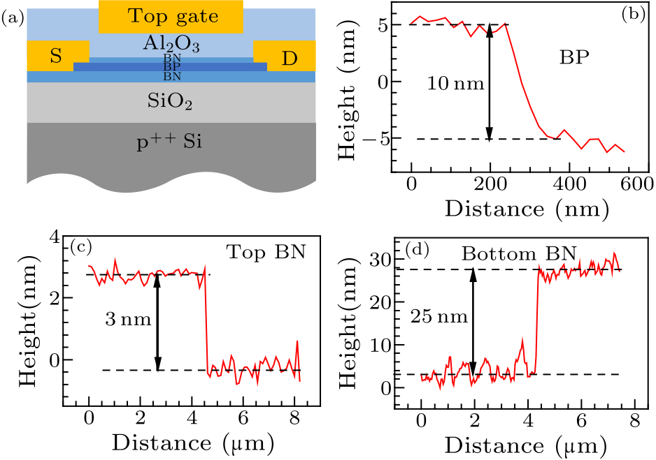
Citation Text: Yan S L, Xie Z J, Chen J H, Taniguchi T and Watanabe K 2017 Chin. Phys. Lett. 34 047304 Abstract The energy bandgap is an intrinsic character of semiconductors, which largely determines their properties. The ability to continuously and reversibly tune the bandgap of a single device during real time operation is of great importance not only to device physics but also to technological applications. Here we demonstrate a widely tunable bandgap of few-layer black phosphorus (BP) by the application of vertical electric field in dual-gated BP field-effect transistors. A total bandgap reduction of 124 meV is observed when the electrical displacement field is increased from 0.10 V/nm to 0.83 V/nm. Our results suggest appealing potential for few-layer BP as a tunable bandgap material in infrared optoelectronics, thermoelectric power generation and thermal imaging. DOI:10.1088/0256-307X/34/4/047304 PACS:73.63.-b, 73.20.At, 85.35.-p © 2017 Chinese Physics Society Article Text Few-layer black phosphorus (BP) or phosphorene when down to a single layer, a new member recently added to the two dimensional material family, has been intensively investigated due to the great potential for applications in nano-electronics,[1-7] opto-electronics,[2,8-12] bio-medical therapy,[13-17] energy storage,[18,19] gas sensors,[20] etc. The bandgap of black phosphorus is dependent on the flake thickness, ranging from 0.3 eV for bulk crystals to 2 eV in monolayer phosphorene.[5,21,22] While this property is unique and potentially useful,[23] the energy bandgap is fixed for a particular device. Various ways has been used to achieve bandgap tuning of a single black phosphorus crystal such as in situ potassium doping and the application of strain or high pressure.[24-26] In real world applications, however, the ability to change the bandgap in a single device during its operation is highly desirable. For few-layer BP, the application of vertical electrical field is an attractive option, because this method should preserve the mobility of the device while allowing precise, continuous and reversible modification of the bandgap[27-32] owing to the giant Stark effect.[24,33] It was reported theoretically that the bandgap of BP decreases monotonously with the vertical displacement electrical field and eventually reaches zero at a critical field.[34-37] Unfortunately, experimental results are still lacking$^†$. In this work, we report the electrically tunable bandgap of few-layer BP in dual-gated field effect transistors. By applying top and bottom gating simultaneously, we were able to tune the Fermi energy and electrical displacement field independently. The measured energy bandgap $E_{\rm g}$ exhibits a pronounced decrease with increasing displacement field. First, we introduce the fabrication details of our dual-gated few-layer BP field-effect transistors (FETs). Bulk black phosphorus crystals were bought from HQ-graphene Inc., and h-BN bulk crystals are grown by the method described in Ref. [38]. Few-layer black phosphorus was mechanically exfoliated using scotch-tape and PDMS slab. BN was cleaved using scotch-tape only. Various efforts have been made to encapsulate BP devices to improve its environmental stability. Among them, atomic layer deposition (ALD) of Al$_{2}$O$_{3}$ is a widely chosen method due to its technical maturity and the high quality of the encapsulating layer.[39-41] However, it has been reported that the deposition of Al$_{2}$O$_{3}$ on BP may lead to the oxidation of BP.[42] Due to the chemically active nature of BP, it is difficult to avoid oxidation during device fabrication completely, resulting in the deterioration of device performance after ALD deposition of Al$_{2}$O$_{3}$.[43] Here we capped the BP channel with ultra-thin BN with the pick-up dry transfer method[44] under inner atmosphere before the ALD deposition of Al$_{2}$O$_{3}$ to protect the BP channel from oxidation in subsequent micro-fabrication process. The electrodes of the device were defined by sequential e-beam lithography and e-beam evaporation of Cr/Au. A second e-beam lithography was used to pattern the Hall bar geometry, the exposed BP was etched by reactive ion etching (RIE) with ${\rm CF}_{\rm 4}$ for 85 s with a power of 10 W. Prior to the Al$_{2}$O$_{3}$ layer growth by ALD, we deposited a 1–2 nm thick Al layer on the devices surface by e-beam evaporation. The Al layer was oxidized in atmosphere and served as a seeding layer. Afterwards, a 100 nm Al$_{2}$O$_{3}$ was deposited with trimethylaluminum (TMA) and H$_{2}$O as precursors at 200$^{\circ}\!$C. Finally, the top gate was made by the same technique as the electrode as mentioned above. All the fabrication and measurement process are carried out in inert atmosphere, or with the sample capped with a protection layer. The thickness of BP was roughly determined by an optical microscope before device fabrication then accurately measured using an atomic force microscope (AFM) after all transport measurements. The schematic view of the device is shown in Fig. 1(a). The thicknesses of the BP flake, the top BN and the bottom BN are 10 nm, 3 nm and 25 nm, respectively (Figs. 1(b), 1(c) and 1(d)).
cpl-34-4-047304-fig1.png
Fig. 1. Dual-gated few-layer BP FET and AFM data of top BN, BP channel and bottom BN. (a) Schematic view of a dual-gated few-layer black phosphorus (BP) FET. (b) Atomic force microscope (AFM) image of the same device. The thicknesses of the bottom BN, the black phosphorus flake and the top BN are 25 nm, 10 nm and 3 nm, respectively.
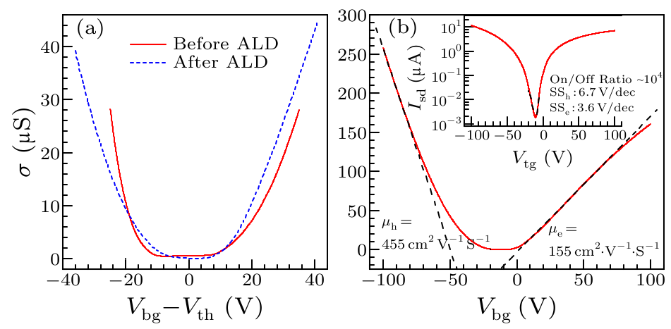
We characterized our dual-gated device by comparing the transfer curve before and after the deposition of the 100-nm Al$_{2}$O$_{3}$ film (Fig. 2(a)). The transfer curves measured before ALD (red line) and after ALD (blue line) exhibit minimal changes for their overall shapes, indicating the effectiveness of the BN protection layer. Our data is measured at room temperature unless noted otherwise. The switching property of our dual-gated device to the back gate (top gate grounded) shows a clear ambipolar behavior with n-type doping at zero gate voltage as illustrated in Fig. 2(b). The on/off ratio, defined as the ratio of the maximum and minimum measured $I_{\rm sd}$ from the transfer curve is greater than 10$^{4}$ for both electrons and holes. The field effect mobility is calculated from the linear region of the transfer characteristics (black dashed lines in Fig. 2(b)), according to the equation $$ \mu _{\rm FE} = \frac{1}{C_{\rm bg} }\frac{d\sigma }{dV_{\rm bg} },~~ \tag {1} $$ with $$\sigma = \frac{L}{W}\frac{I_{\rm sd} }{V_{\rm sd}}, $$ where $\sigma$ is the sheet conductivity of the device, $L$ = 14 μm and $W$ = 6.2 μm are the length and width of the channel, respectively. We obtain a hole-mobility as high as 455 ${\rm cm}^{\rm 2}{\rm V}^{\rm -1}{\rm s}^{\rm -1}$, which would be higher if we use the four-terminal measurements to eliminate the effect of contact resistance. The hole mobility $\mu _h$ acquired here is one of the highest values among the Al$_{2}$O$_{3}$-passivated BP FETs[40,41,45-47] measured at room temperature, probably due to the protection of the top BN. The electron mobility $\mu _{\rm e}$ is 155 ${\rm cm}^{\rm 2}{\rm V}^{\rm -1}{\rm s}^{\rm -1}$, similar to the values extracted from the high-quality BP FETs in other papers.[48] The subthrehold swing (SS) is about 6.7 V/dec for holes and 3.6 V/dec for electrons as shown in the inset of Fig. 2(b).
cpl-34-4-047304-fig2.png
Fig. 2. Device performance. (a) Sheet conductivity measured as a function of $V_{\rm bg}$ before and after ALD deposition at room temperature. (b) Sheet conductivity measured as a function of $V_{\rm bg}$ with top gate grounded at room temperature. The field-effect mobilities for electrons and holes are obtained from the line fit of the linear part of the transfer curve (dashed lines), respectively. The mobility is 455 ${\rm cm}^{\rm 2}{\rm V}^{\rm -1}{\rm s}^{\rm -1}$ for holes and 155 ${\rm cm}^{\rm 2}{\rm V}^{\rm -1}{\rm s}^{\rm -1}$ for electrons. The inset shows the transfer curve of $I_{\rm sd}$ versus $V_{\rm bg}$ for $V_{\rm sd} =20\,{\rm mV}$ in a semi-log plot.
Figure 3(a) shows the room-temperature conductance of the dual-gated few-layer BP FET as a function of top gate voltage with several different back gate voltages from $-$60 V to 60 V, with steps of 5 V. The source drain bias is 20 mV. It can be seen that for $V_{\rm bg} > -10$ V, the device shows an ambipolar n-type behavior; for $V_{\rm bg} < -10$ V, the device shows p-type behavior. Specifically, for $V_{\rm bg} < -20$ V unipolar behavior has been observed, e.g., an on-state of the device at the electron side was not observed in the explored range of the top and bottom gate voltages. This can be explained by the fact that multiple serial p–n junctions are formed in the device for $V_{\rm bg} < -20$ V, which greatly suppresses the conductivity of the BP channel. Figure 3(b) shows the relation between $V_{\rm bg}$ and $V_{\rm tg}$ at the minimum conductivity $\sigma _{\rm min}$, and the red dashed line is the linear fit to the data. It can be seen that the linearity of the data is quite well, suggesting very good performance of the dual-gated device. The slope of the linear fit gives the ratio of capacitance of the top gate and bottom gate dielectrics, which is approximately 4. The dielectric constant of top gate is calculated to be 5.2 according to the equation $$ \frac{C_{\rm TG} }{C_{\rm BG} }=\frac{\varepsilon _{{\rm TG}\ast d_{\rm BG}}}{\varepsilon _{{\rm BG}\ast d_{\rm TG}}}. $$ For dual-gated FETs, the carrier doping ($\delta n$) and the vertical electrical displacement field ($D_{\rm ave}$) can be tuned independently. Here we define the top and bottom electrical displacement fields as $D_{\rm t} =-\frac{\varepsilon _{\rm t} V_{\rm tg} }{d_{\rm t}}$ and $D_{\rm b} =+\frac{\varepsilon _{\rm b} V_{\rm bg} }{d_{\rm b}}$, where $\varepsilon _{\rm t} =5.2$ and $\varepsilon _d =3.9$ are the relative dielectric constant of the top gate and the bottom gate, respectively; $d_{\rm t}$ (103 nm) and $d_{\rm b}$ (325 nm) are the thicknesses of the dielectric layer of top gate and bottom gate, respectively. Here we made a highly accurate approximation, assuming that the difference in dielectric constant of the ultra-thin top BN from that of the Al$_{2}$O$_{3}$ does not affect the capacitance of the top gate dielectric significantly, and the dielectric constants of SiO$_{2}$ and the bottom BN are nearly the same. Then $\delta n\propto ({D_{\rm b} -D_{\rm t} })$ and $D_{\rm ave} =({D_{\rm b} +D_{\rm t} })/2$, respectively.[28] Figure 3(c) plots $\sigma _{\rm min}$ versus $D_{\rm ave}$. The $\sigma _{\rm min}$ changes substantially from 0.09 μS to 1.37 μS when $D_{\rm ave}$ varies from 0.04 V/nm to 0.98 V/nm, suggesting a bandgap reduction in our few-layer BP device under vertical displacement field.[27-29]
cpl-34-4-047304-fig3.png
Fig. 3. Transport characteristics of the dual-gated few-layer BP FET. (a) Conductivity measured as a function of the top gate voltage with different $V_{\rm bg}$ from $-$60 V to 60 V, at steps of 5 V. The source drain bias is 20 mV. (b) The relation between $V_{\rm bg}$ and $V_{\rm tg}$ at the minimum conductivity, and the red dashed line is the linear fit to the data. (c) Minimum conductivity as a function of the averaged displacement field $D_{\rm ave}$.
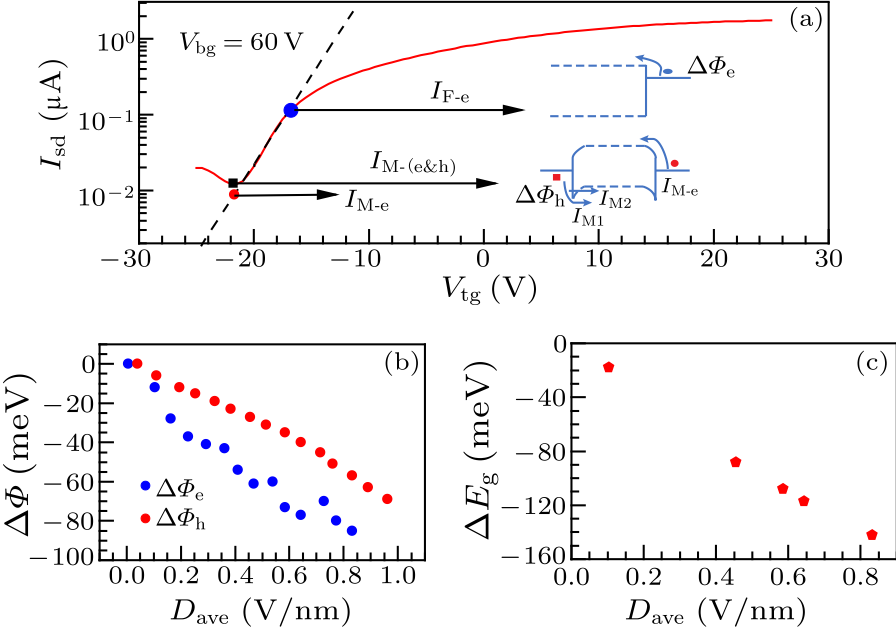
Next, we extract the change of Schottky barrier height of the contact at the flat band. The flat band condition refers to the situation when there is no charge accumulation at the contact and BP junction and that the band diagram of the few-layer BP is flat over the whole device,[49] which usually happens at a specific gate voltage $V_{\rm g\_flat}$. For n-type FETs, when $V_{\rm g} < V_{\rm g\_flat}$ and with the Fermi level $E_{\rm F} > E_{\rm v}$ (the energy of the valence band edge), the injection current is dominated by thermal excitation of electrons from the metal contact to the conduction band of the semiconductor, leading to an exponential dependence between $I_{\rm ds}$ and $V_{\rm g}$. Hence $V_{\rm g\_flat}$ is the specific gate voltage where $\log I_{\rm ds} \propto \log \sigma$ versus $V_{\rm tg}$ deviates from linearity, as shown in Fig. 4(a). The source-drain current $I_{\rm ds}$ at $V_{\rm g\_flat}$ can be used to calculate the Schottky barrier height of electrons using the following equations[21] $$\begin{align} &I_{\rm F} =q \int \limits_\infty ^{{\it\Phi} _{\rm e} } M({E-{\it\Phi} _{\rm e} })f( E)dE,~~ \tag {2} \end{align} $$ $$\begin{align} &M(E)=\frac{2}{h^2}\sqrt {2m_{\rm e} E},~~f(E)=\frac{1}{1+{\rm exp}({\frac{E}{k_{_{\rm B}}\! T}})}.~~ \tag {3} \end{align} $$ We use Eqs. (2) and (3) to obtain the change of Schottky barrier height of electrons as a function of $D_{\rm ave}$, as shown in Fig. 4(b). In addition, we can calculate the Schottky barrier heights to the valence band edge from the minimum conductance. At the minimum conductance, the current is comprised of the electron current $I_{\rm M\_{\rm e}}$ injected from the drain electrode and the hole current $I_{\rm M\_h}$ injected from the source electrode, i.e., $I =I_{\rm M\_{\rm e}}$ $+ I_{\rm M\_h}$. As $I_{\rm M\_{\rm e}}$ consists of only the thermally activated current, it can be estimated by the interpolation of the linear fit of $\log I_{\rm ds} \propto \log \sigma$ as a function of $V_{\rm tg}$ at $V_{\rm M}$, as depicted in Fig. 4(a). $I_{\rm M\_h}$, on the other hand, is composed of (1) the thermally activated current over the Schottky barrier ($I_{\rm M1}$) and (2) the activated thermionic emission current through a triangular potential barrier ($I_{\rm M2}$). Thus $I_{\rm M\_h}$ $=I_{\rm M1}$ $+ I_{\rm M2}$ can be expressed as[21] $$\begin{align} I_{\rm M1} =q \int \limits_{{\it\Phi} _h }^\infty M({E+\phi _{\rm drive} -{\it\Phi} _h })f(E)dE,~~ \tag {4} \end{align} $$ $$\begin{align} I_{\rm M2} =q \int \limits_{{\it\Phi} _{h}-\phi _{\rm drive} }^{-{\it\Phi} _{\rm SB1} } \!\!\!\!\!M( {E\!+\!\phi _{\rm drive}\!-\!\phi _h })T_{\rm WKB} (E)f(E)dE ,~~ \tag {5} \end{align} $$ $$\begin{align} T_{\rm WKB} ={\rm exp}\Big({-\frac{8\pi }{3h}\sqrt {2m_{\rm e} ({{\it\Phi} _h -E})^3} \frac{\lambda }{\phi _{\rm drive} }}\Big) ,~~ \tag {6} \end{align} $$ $$\begin{align} \lambda \approx \sqrt {t_{\rm ox} t_{\rm body} },~~~~\phi _{\rm drive} =qV_{\rm ds} + \Delta {\it\Phi} ,~~ \tag {7} \end{align} $$ where $t_{\rm ox}$ and $t_{\rm body}$ are the thicknesses of the Al$_{2}$O$_{3}$ oxide (100 nm) and channel BP (10 nm), respectively. $\Delta {\it\Phi}$ is the band bending compared with the flat band. The tunneling probability $T_{\rm WKB}$ is calculated using the WKB approximation. Considering the rather small source drain bias we applied, $\phi _{\rm drive}$ is estimated to be smaller than $E_{\rm g}$, and the tunneling current $I_{\rm M2}$ is the result of electron tunneling through an approximately triangle barrier. Using the above method, we can obtain the changes of Schottky barrier heights of electrons ($\Delta {\it\Phi}_{\rm e}$) and holes ($\Delta {\it\Phi}_{\rm h}$) as a function of $D_{\rm ave}$, as shown in Fig. 4(b). Because $\Delta {\it\Phi}_{\rm e}$ and $\Delta {\it\Phi}_{\rm h}$ are obtained at different values of $V_{\rm tg}$ and $V_{\rm bg}$, they generally have different $D_{\rm ave}$ values. Among the data we have collected, we are able to find $\Delta {\it\Phi}_{\rm e}$ ($D_{\rm ave}$) and $\Delta {\it\Phi}_{\rm e}$ ($D_{\rm ave}$) that have almost the same $D_{\rm ave}$ (difference in $D_{\rm ave}$ within 0.01 V/nm). Thus we obtain $\Delta E_{\rm g} = \Delta {\it\Phi}_{\rm e} + \Delta {\it\Phi}_{\rm h}$ for such data points, as shown in Fig. 4(c). We can conclude that the bandgap can be tuned continuously by the vertical electric field, and the tuning magnitude of the bandgap is approximately 124 meV when $D_{\rm ave}$ varies from 0.10 V/nm to 0.83 V/nm.
cpl-34-4-047304-fig4.png
Fig. 4. Tuning of the bandgap of few-layer BP. (a) Transfer characteristics tuned by the top gate at a back gate voltage of 60 V. The inset illustrates the band diagrams under the flat band condition (upper) and the minimum conductivity condition (lower) at $V_{\rm bg}$=60 V. (b) The change of Schottky barrier of electrons and holes by the electrical displacement field. (c) The estimated bandgap modification as a function of the averaged displacement field.
Several theoretical works have focused on the effects induced by an external vertical electric field on black phosphorus. All those theoretical studies demonstrated that the energy bandgap of black phosphorus experiences a monotonously reduction with the increase of the displacement field,[34,35,37] which agrees with our experimental results. Novel physics such as transition from normal insulator to topological insulator which provides the opportunity to realize "field effect topological transistor"[35] and spin-polarized Dirac cones whose position and carrier velocity can be tuned by the electric field[34] were predicted. We believe these interesting physical phenomena can be realized in experiments through the use of dielectric layers that have higher gating capability, such as ionic liquid or ferroelectric insulators. The high quality of the devices would be preserved by using the ultra-thin h-BN protecting technique as demonstrated in this work. Next, we discuss the possible factors that affect the accuracy of our calculation in the text. First of all, because the source drain electrode is deposited on top of the sample, a very small regime of BP nears the source and drain electrodes may not be effectively tuned by the top gate due to screening of the source-drain electrodes. So there will be an additional barrier for charge carrier injection when there are additional p–n junctions formed. However, the effect is relatively small since the channel of the device is fully covered by the top gate electrode. The second point worth noting is that the bandgap varies as the top gate voltage moves from the minimum conductivity condition to the flat band condition, which could affect the determination of the position of $V_{\rm F}$. Nevertheless, the change of $D_{\rm ave}$ between the flat band condition and the minimum conductivity point is relatively small, thus the dependence of $\Delta E_{\rm g}$ versus $D_{\rm ave}$ can be considered to be linear,[34] and will not affect our calculations. Last but not the least, in order to evaluate the impact of the Stark effect on the results of our calculation, we extract the field effect mobility from Fig. 3(a). We find that the mobility increases about five times as $V_{\rm bg}$ varies from 0 V to 60 V, which may be attributed to three effects: the first one is the impact of the vertical electric field on the effective mass of the carriers,[37] which may contribute to the observed increase of the mobility in our experiment; the second one is the change of the Schottky barrier height, which has been considered in our calculation; and the last one is the charge redistribution corresponding to the electric field.[50,51] Note that, unlike carrier mobility, the minimum conductivity experiences an almost ten times increase as $V_{\rm bg}$ varies from 0 V to 60 V. So our result indeed demonstrates the electric field induced energy bandgap engineering in few-layer black phosphorus. In conclusion, we have demonstrated in-operation bandgap engineering of few-layer BP by vertical electric field. The bandgap is estimated to be reduced by 124 meV when $D_{\rm ave}$ varies from 0.10 V/nm to 0.83 V/nm, illustrating the opportunity for realizing the bandgap closing in dual-gated BP devices through reversible, electric field effects. Our results not only broaden applications of few-layer BP FETs in nanoelectronics, optoelectronics, and photonics, but also provide the platform for the investigation of the physics of Dirac fermions[24,26] and topological insulators[35] in two-dimensional BP devices. $†$After completion of this work, we found an independent report on the tuning of energy bandgap of dual-gate black phosphorus devices by Professor Feng-Nian Xia et al.[52] who used different methods to reach the similar conclusions. Correspondence and requests for materials and data should be addressed to Shi-Li Yan (yanshili@pku.edu.cn) and Jian-Hao Chen (chenjianhao@pku.edu.cn). Jian-Hao Chen conceived the project. Shi-Li Yan fabricated the devices, performed the transport measurements, and analyzed the data. Zhi-Jian Xie calculated the energy bandgap value. Jian-Hao Chen, Shi-Li Yan and Zhi-Jian Xie wrote the paper together. All the authors discussed the results and commented on the manuscript. The authors declare no competing financial interests. We thank Professor Xiao-Song Wu from Peking University for the use of the ALD machine. We also thank Professor Feng-Nian Xia from Yale University for useful discussions.
References Black phosphorus field-effect transistorsRediscovering black phosphorus as an anisotropic layered material for optoelectronics and electronicsPhosphorene: An Unexplored 2D Semiconductor with a High Hole MobilityHigh-mobility transport anisotropy and linear dichroism in few-layer black phosphorusLayer-controlled band gap and anisotropic excitons in few-layer black phosphorusElectric field effect in ultrathin black phosphorusStrain-Engineering the Anisotropic Electrical Conductance of Few-Layer Black PhosphorusFast and Broadband Photoresponse of Few-Layer Black Phosphorus Field-Effect TransistorsPhotovoltaic effect in few-layer black phosphorus PN junctions defined by local electrostatic gatingBroadband nonlinear optical response in multi-layer black phosphorus: an emerging infrared and mid-infrared optical materialBlack Phosphorus Photodetector for Multispectral, High-Resolution ImagingMechanically exfoliated black phosphorus as a new saturable absorber for both Q-switching and Mode-locking laser operationBlack Phosphorus Nanosheets as a Robust Delivery Platform for Cancer TheranosticsBiodegradable black phosphorus-based nanospheres for in vivo photothermal cancer therapyBlack Phosphorus Nanosheet-Based Drug Delivery System for Synergistic Photodynamic/Photothermal/Chemotherapy of CancerUltrasmall Black Phosphorus Quantum Dots: Synthesis and Use as Photothermal AgentsUltrathin Black Phosphorus Nanosheets for Efficient Singlet Oxygen GenerationBlack Phosphorus and its Composite for Lithium Rechargeable BatteriesElectrochemical Activity of Black Phosphorus as an Anode Material for Lithium-Ion BatteriesBlack Phosphorus Gas SensorsCorrection to Tunable Transport Gap in PhosphoreneSemiconducting black phosphorusCorrection to “Black Phosphorus: Narrow Gap, Wide Applications”Observation of tunable band gap and anisotropic Dirac semimetal state in black phosphorusStrain-Induced Gap Modification in Black PhosphorusPressure-Induced Electronic Transition in Black PhosphorusElectrically Tunable Bandgaps in Bilayer MoS 2Direct observation of a widely tunable bandgap in bilayer grapheneGraphene Field-Effect Transistors with High On/Off Current Ratio and Large Transport Band Gap at Room TemperatureCharge Transport in Dual Gated Bilayer Graphene with Corbino GeometryTopological origin of subgap conductance in insulating bilayer grapheneElectronic Transport in Dual-Gated Bilayer Graphene at Large Displacement FieldsTuning the electronic properties of boron nitride nanotubes with transverse electric fields: A giant dc Stark effectElectric-field tunable Dirac semimetal state in phosphorene thin filmsSwitching a Normal Insulator into a Topological Insulator via Electric Field with Application to PhosphorenePhosphorene Nanoribbons, Phosphorus Nanotubes, and van der Waals MultilayersModulation of the Electronic Properties of Ultrathin Black Phosphorus by Strain and Electrical FieldSynthesis of high-purity boron nitride single crystals under high pressure by using Ba–BN solventToward air-stable multilayer phosphorene thin-films and transistorsFew-Layer Black Phosphorus Field-Effect Transistors with Reduced Current FluctuationDual Gate Black Phosphorus Field Effect Transistors on Glass for NOR Logic and Organic Light Emitting Diode SwitchingAl 2 O 3 on Black Phosphorus by Atomic Layer Deposition: An in Situ Interface StudyEffective Passivation of Exfoliated Black Phosphorus Transistors against Ambient DegradationOne-Dimensional Electrical Contact to a Two-Dimensional MaterialAmbipolar Black Phosphorus MOSFETs With Record n-Channel TransconductanceTemporal and Thermal Stability of Al 2 O 3 -Passivated Phosphorene MOSFETsCorrection to Ambipolar Phosphorene Field Effect TransistorQuantum oscillations in a two-dimensional electron gas in black phosphorus thin filmsPhysics of Semiconductor DevicesGate-tunable phase transitions in thin flakes of 1T-TaS2Stark-effect scattering in rough quantum wells
[1] Li L, Yu Y, Ye G J, Ge Q, Ou X, Wu H, Feng D, Chen X H and Zhang Y 2014 Nat. Nanotechnol. 9 372
[2] Xia F, Wang H and Jia Y 2014 Nat. Commun. 5 4458
[3] Liu H, Neal A T, Zhu Z, Luo Z, Xu X F, Tomanek D and Ye P D 2014 ACS Nano 8 4033
[4] Qiao J S, Kong X H, Hu Z X, Yang F and Ji W 2014 Nat. Commun. 5 4475
[5] Tran V, Soklaski R, Liang Y F and Yang L 2014 Phys. Rev. B 89 235319
[6] Koenig S P, Doganov R A, Schmidt H, Castro Neto A H and Oezyilmaz B 2014 Appl. Phys. Lett. 104 10
[7] Fei R X and Yang L 2014 Nano Lett. 14 2884
[8] Buscema M, Groenendijk D J, Blanter S I, Steele G A, van der Zant H S J and Castellanos-Gomez A 2014 Nano Lett. 14 3347
[9] Buscema M, Groenendijk D J, Steele G A, van der Zant H S J and Castellanos-Gomez A 2014 Nat. Commun. 5 4651
[10] Lu S B, Miao L L, Guo Z N, Qi X, Zhao C J, Zhang H, Wen S C, Tang D Y and Fan D Y 2015 Opt. Express 23 11183
[11] Engel M, Steiner M and Avouris P 2014 Nano Lett. 14 6414
[12] Chen Y, Jiang G B, Chen S Q, Guo Z N, Yu X F, Zhao C J, Zhang H, Bao Q L, Wen S C, Tang D Y and Fan D Y 2015 Opt. Express 23 12823
[13] Tao W, Zhu X, Yu X, Zeng X, Xiao Q, Zhang X, Ji X, Wang X, Shi J, Zhang H and Mei L 2017 Adv. Mater. 29 1603276
[14] Shao J, Xie H, Huang H, Li Z, Sun Z, Xu Y, Xiao Q, Yu X F, Zhao Y, Zhang H, Wang H and Chu P K 2016 Nat. Commun. 7 12967
[15] Chen W, Ouyang J, Liu H, Chen M, Zeng K, Sheng J, Liu Z, Han Y, Wang L, Li J, Deng L, Liu Y N and Guo S 2017 Adv. Mater. 29 1603864
[16] Sun Z, Xie H, Tang S, Yu X F, Guo Z, Shao J, Zhang H, Huang H, Wang H and Chu P K 2015 Angew. Chem. Int. Ed. 54 11526
[17] Wang H, Yang X Z, Shao W, Chen S C, Xie J F, Zhang X D, Wang J and Xie Y 2015 J. Am. Chem. Soc. 137 11376
[18] Park C M and Sohn H J 2007 Adv. Mater. 19 2465
[19] Sun L Q, Li M J, Sun K, Yu S H, Wang R S and Xie H M 2012 J. Phys. Chem. Lett. 116 14772
[20] Abbas A N, Liu B, Chen L, Ma Y, Cong S, Aroonyadet N, Koepf M, Nilges T and Zhou C 2015 ACS Nano 9 5618
[21] Das S, Zhang W, Demarteau M, Hoffmann A, Dubey M and Roelofs A 2016 Nano Lett. 16 2122
[22] Morita A 1986 Appl. Phys. A 39 227
[23] Castellanos-Gomez A 2015 J. Phys. Chem. Lett. 6 4873
[24] Kim K S, Kim J, Baik S S, Ryu S H, Sohn Y, Park S, Park B G, Denlinger J, Yi Y, Choi H J and Kim K S 2015 Science 349 723
[25] Rodin A S, Carvalho A and Castro Neto A H 2014 Phys. Rev. Lett. 112 176801
[26] Xiang Z J, Ye G J, Shang C, Lei B, Wang N Z, Yang K S, Liu D Y, Meng F B, Luo X G, Zou L J, Sun Z, Zhang Y and Chen X H 2015 Phys. Rev. Lett. 115 186403
[27] Chu T, Ilatikhameneh H, Klimeck G, Rahman R and Chen Z 2015 Nano Lett. 15 8000
[28] Zhang Y, Tang T T, Girit C, Hao Z, Martin M C, Zettl A, Crommie M F, Shen Y R and Wang F 2009 Nature 459 820
[29] Xia F, Farmer D B, Lin Y M and Avouris P 2010 Nano Lett. 10 715
[30] Yan J and Fuhrer M S 2010 Nano Lett. 10 4521
[31] Li J, Martin I, Buettiker M and Morpurgo A F 2011 Nat. Phys. 7 38
[32] Taychatanapat T and Jarillo-Herrero P 2010 Phys. Rev. Lett. 105 166601
[33] Khoo K H, Mazzoni M S C and Louie S G 2004 Phys. Rev. B 69 201401
[34] Ghosh B, Singh B, Prasad R and Agarwal A 2016 Phys. Rev. B 94 205426
[35] Liu Q H, Zhang X W, Abdalla L B, Fazzio A and Zunger A 2015 Nano Lett. 15 1222
[36] Guo H, Lu N, Dai J, Wu X and Zeng X C 2014 J. Phys. Chem. C 118 14051
[37] Li Y, Yang S and Li J 2014 J. Phys. Chem. C 118 23970
[38] Taniguchi T and Watanabe K 2007 J. Cryst. Growth 303 525
[39] Kim J S, Liu Y N, Zhu W N, Kim S, Wu D, Tao L, Dodabalapur A, Lai K and Akinwande D 2015 Sci. Rep. 5 8989
[40] Na J, Lee Y T, Lim J A, Hwang D K, Kim G T, Choi W K and Song Y W 2014 ACS Nano 8 11753
[41] Kim J S, Jeon P J, Lee J, Choi K, Lee H S, Cho Y, Lee Y T, Hwang D K and Im S 2015 Nano Lett. 15 5778
[42] Zhu H, McDonnell S, Qin X Y, Azcatl A, Cheng L X, Addou R, Kim J, Ye P D and Wallace R M 2015 ACS Appl. Mater. Interfaces 7 13038
[43] Wood J D, Wells S A, Jariwala D, Chen K S, Cho E, Sangwan V K, Liu X, Lauhon L J, Marks T J and Hersam M C 2014 Nano Lett. 14 6964
[44] Wang L, Meric I, Huang P Y, Gao Q, Gao Y, Tran H, Taniguchi T, Watanabe K, Campos L M, Muller D A, Guo J, Kim P, Hone J, Shepard K L and Dean C R 2013 Science 342 614
[45] Haratipour N and Koester S J 2016 IEEE Electron Device Lett. 37 103
[46] Luo X, Rahbarihagh Y, Hwang J C M, Liu H, Du Y and Ye P D 2014 IEEE Electron Device Lett. 35 1314
[47] Das S, Demarteau M and Roelofs A 2016 ACS Nano 10 2984
[48] Li L, Ye G J, Tran V, Fei R, Chen G, Wang H, Wang J, Watanabe K, Taniguchi T, Yang L, Chen X H and Zhang Y 2015 Nat. Nanotechnol. 10 608
[49] Sze S M and Ng K K 2006 Physics Of Semiconductor Devices (New York: John Wiley & Sons) Chap 3 p 185
[50] Yu Y, Yang F, Lu X F, Yan Y J, Cho Y H, Ma L, Niu X, Kim S, Son Y W, Feng D, Li S, Cheong S W, Chen X H and Zhang Y 2015 Nat. Nanotechnol. 10 270
[51] Jana R K and Jena D 2011 Appl. Phys. Lett. 99 012104
[52]Deng B, Tran V, Jiang H, Li C, Xie Y T, Guo Q, Wang X, Tian H, Wang H, Cha J J, Xia Q, Yang L and Xia F N 2016 arXiv:1612.04475[cond-mat.mes-hall]