Chinese Physics Letters, 2021, Vol. 38, No. 7, Article code 076501 Thermal Stability of High Power 26650-Type Cylindrical Na-Ion Batteries Quan Zhou (周权)1,2, Yuqi Li (李钰琦)1,2, Fei Tang (汤菲)3, Kaixuan Li (李凯旋)3, Xiaohui Rong (容晓辉)1,2, Yaxiang Lu (陆雅翔)1,2*, Liquan Chen (陈立泉)1,2, and Yong-Sheng Hu (胡勇胜)1,2,3* Affiliations 1Key Laboratory for Renewable Energy, Beijing Key Laboratory for New Energy Materials and Devices, Beijing National Laboratory for Condensed Matter Physics, Institute of Physics, Chinese Academy of Sciences, Beijing 100190, China 2Center of Materials Science and Optoelectronics Engineering, University of Chinese Academy of Sciences, Beijing 100049, China 3HiNa Battery Technology Co., Ltd, Beijing 100194, China Received 20 April 2021; accepted 25 May 2021; published online 3 July 2021 Supported by the National Key Technology R&D Program of China (Grant No. 2016YFB0901500), the National Natural Science Foundation of China (Grant No. 51725206), NSFCUKRI_EPSRC (Grant No. 51861165201), the Strategic Priority Research Program of the Chinese Academy of Sciences (Grant No. XDA21070500), and Beijing Natural Science Fund-Haidian Original Innovation Joint Fund (Grant No. L182056).
*Corresponding authors. Email: yxlu@iphy.ac.cn; yshu@iphy.ac.cn
Citation Text: Zhou Q, Li Y Q, Tang F, Li K X, and Rong X H et al. 2021 Chin. Phys. Lett. 38 076501    Abstract As a new electrochemical power system, safety (especially thermal safety) of Na-ion batteries (NIBs) is the key towards large-scale industrialization and market application. Thus, research on the thermal stability of NIBs is helpful to evaluate the safety properties and to provide effective strategies to prevent the occurrence of battery safety failure. Thermal stability of the high-power 26650 cylindrical NIBs using Cu-based layered oxide cathode and hard carbon anode is studied. The high power NIBs can achieve fast charge and discharge at 5–10 C rate and maintain 80% capacity after 4729 cycles at 2 C/2 C rate, where the unit C denotes a measure of the rate at which a battery is charge-discharged relative to its maximum capacity. The results of accelerating rate calorimeter and differential scanning calorimetry (ARC-DSC) test results show that NIBs have a higher initial decomposition temperature ($\ge$110 ℃) and a lower maximum thermal runaway temperature ($\le $350 ℃) than those of Li-ion batteries (LIBs), exhibiting a favorable thermal stability. It should be noted that the heat generation of cathode accounts for a large proportion of the total heat generation while the thermal stability of the anode determines the initial thermal runaway temperature, which is similar to LIBs. Finally, the whole temperature characteristics of the NIBs in the range of $-60 $ ℃–1000 ℃ are summarized, which provide guidance for the safety design and applications of NIBs. DOI:10.1088/0256-307X/38/7/076501 © 2021 Chinese Physics Society Article Text Development of Na-ion batteries (NIBs) with abundant resources can alleviate the restricted application of Li-ion batteries (LIBs) in large-scale energy storage caused by the shortage and uneven distribution of lithium resources.[1–3] NIBs have received extensive attention of academia and industry, gradually beginning their commercialization progress. Although the energy density still exists a certain gap compared with the current LIBs, NIBs have the unique advantages in terms of power and cycle performance. On the one hand, NIBs using disordered carbon materials can realize faster Na$^{+}$ insertion and extraction as well as stable cycling.[4,5] On the other hand, NIBs with polar solvent have a lower desolvation energy [e.g., Na: 158.2 kJ/mol, Li: 215.8 kJ/mol, in propylene carbonate (PC) solvent] and a smaller ionic stokes radius (e.g., Na: 4.6 Å, Li: 4.8 Å, in PC solvent) than those of LIBs,[6,7] so Na$^{+}$ has a faster kinetics and a higher conductivity in the electrolyte and electrode/electrolyte interface. Therefore, NIBs have the potential to achieve fast charge-discharge, which endows NIBs a greater market competitive advantage over LIBs in frequency modulation energy storage, data center and other applications that are more sensitive to cost and high power. Besides cost and power, safety is another significant indicator to determine the application feasibility of batteries. Common safety accidents are induced by thermal runaway due to the safety failure of batteries.[8,9] Therefore, it is urgent to study the thermal stability of NIBs to demonstrate and reveal their safety characteristics from the intrinsic point of view. Because of the similar battery structure and working principle to LIBs, related research methods can refer to and learn from the LIBs. Accelerating rate calorimeter (ARC) is usually used to study the thermal stability of fresh and failed batteries,[10–12] and differential scanning calorimetry (DSC) is commonly used to determine the thermal stability of cathode materials, anode materials, separators, electrolytes, binders, etc.[13–16] However, there are few reports on thermal stability of NIBs, especially high-power NIBs qualified for commercial applications. Similar to LIBs, in the process of NIBs thermal runaway the source of heat also derives from multiple aspects, mainly including the decompositions of solid electrolyte interphase (SEI),[17] cathode material, electrolyte and separator, which may cause side reactions between each other, so it is difficult to distinguish the generated heat during the reaction of thermal runaway.[18] In order to analyze the main sources of heat during the process of thermal runaway, Ouyang et al.[18] proposed a basic thermodynamic system model for battery thermal analysis, where the batteries divided into three parts: cathode + electrolyte, anode + electrolyte and separator + electrolyte are monitored by the DSC device. This method can clearly distinguish the heat sources in different temperature ranges and is helpful for judging the safety of the newly designed batteries. For the anodes, the high temperature degradation mechanism is strongly influenced by the thermal stability of the SEI, which is defined by the electrolyte composition.[19–25] It has been reported that for LIBs, SEI thermal breakdown occurs at about 100 ℃[26–30] due to the decomposition and conversion of thermally unstable organic components.[23,26,29] For the cathodes, especially layered oxide materials such as LiNi$_{0.5}$Co$_{0.2}$Mn$_{0.3}$O$_{2}$, they normally exhibit high reactivity at high temperatures.[26,30,31] Progressive thermal decomposition of the cathode starts at about 200 ℃, leading to the loss of oxygen, which further induces a series of exothermic reactions such as oxidative decomposition of the electrolyte.[26,31–33] Due to the reduced structural stability of the cathode, oxygen release and associated heat generation are correlated with the state of charge (SOC) and the state of health (SOH) of batteries.[30–31] The fast decomposition rate of cathode materials and the accompanying oxygenation of the liquid electrolyte can eventually lead to thermal runaway, and the generated heat cannot be taken away by ambient heat dissipation.[26] On the contrary, the thermal stability of spinel structure (such as LiMn$_{2}$O$_{4}$[34]) or olivine structure (such as LiFePO$_{4}$[30]) is better than that of layered oxide materials. It is noted that many differences exist in thermal stability and thermal runaway degree under different SOH of batteries, therefore it is important to simulate the safety failure mechanism under the actual use situation. In this Letter, we systematically analyze the thermal runaway mechanism and intrinsic safety feature of the high-power 26650 NIBs from the aspects of battery and material, with the hope that it will help researchers and engineers to obtain the updated knowledge for designing safer batteries, helping NIBs to be quickly accepted by the market and promoting the rapid development of NIBs industry. ExperimentsHigh Power 26650-Type Cylindrical NIBs. The batteries investigated in this study were the 26650-type cylindrical NIBs with a nominal capacity of 2300 mA$\cdot$h and an average voltage of 3.0 V. The batteries were fabricated with Cu-based layered oxide (CFM) cathode, hard carbon (HC) anode and 1 M NaPF$_{6}$/EC + PC + DEC electrolyte. The mass loading of cathode was 16 mg/cm$^{2}$ and the capacity ratio of anode to cathode was 1.12 for the 26650-type cylindrical NIBs. All the galvanostatic measurements of the NIBs were performed on a Neware BTS-5V12A battery test system (Shenzhen, China) in the voltage range of 1.5–4.0 V at the temperature of $25 \pm 3$ ℃. The ARC Test. The heat-wait-search (HWS) mode of ARC was chosen to study the thermal response and self-heating rate (SHR, ℃/min) of fresh and aged batteries. First, the battery was heated up until its surface temperature reached 40 ℃. Then, a wait period of 30 min was performed for equilibration. Following that, a seek step started to search for SHR of exothermic reactions above threshold (SHR $> 0.02$ ℃/min). If the temperature of the battery arrived above the threshold, the ARC would switch to exothermic mode to maintain the adiabatic state. As a result, the surface temperature of battery could be tracked. Otherwise, heat mode was performed to increase surface temperature of batteries by 5 ℃. Finally, wait mode, seek mode and heat mode were cycled until the threshold was broken. The experiment would be terminated when the surface temperature of battery reached 350 ℃ or SHR $> 1000 $ ℃/min. The thermocouples were attached to the middle location of battery shell, so the surface temperature of battery during thermal runaway could be detected and recorded. The battery was fixed on an iron holder so that the thermocouple did not come off caused by shaking of battery during thermal runaway. The DSC Test. DSC test is usually used to evaluate the thermal properties of the battery and its chemistry,[13] using instruments manufactured by Netzsch. Thermodynamic properties of the component materials were evaluated by setting suitable temperature scanning rates. The DSC results of the component materials are helpful to reveal the mechanisms responsible for the features of the ARC curves of the battery. The samples consisted of powders scratched from electrodes of the disassembled charged state battery in an argon filled glove box (MBraun). Then, the samples were washed twice with dimethyl carbonate (DMC, 99%, Alfa Aesar) to remove residues of the electrolyte. The electrolyte was refilled into the crucible for the DSC test, as the powder was dried after scratching. The mass ratios of the powder and electrolyte were the same as those in the porous electrodes.[35] The amounts of “cathode : electrolyte : anode” of the 26650 battery tested in this work were 2.33 mg, 2 µL, 2.46 mg, respectively. The DSC tests were conducted from 35 ℃ to 500 ℃ under inert atmosphere at a scanning rate of 5 ℃/min. Results and DiscussionElectrochemical Performance. The rate and cycling performance of the high-power cylindrical 26650 NIBs [Fig. 1(a)] were first studied. Figures 1(b) and 1(c) display the charge-discharge curves of the batteries at different rates, exhibiting a very high discharge capacity at 10 C rate, equivalent to 90% of the discharge capacity at 0.2 C rate, with a corresponding power density of 1250 W/L. At the same time, it can also charge-discharge rapidly at 5 C rate and maintains 80% capacity after 4729 cycles at 2 C/2 C rate [Fig. 1(d)], having a good commercial prospect in high power application field. Safety Test Results of High Power 26650-Type Cylindrical NIBs. Similar to LIBs, the origin of safety problems lies in thermal runaway induced by heat release inside the battery or external damage. The thermal runaway process usually consists of the following three steps:[36,37] (1) The abnormal overheating, overcharge, short circuit, extrusion, nail penetration, impurity particles, electrode plate burr and dendrite growth inside the battery, etc. induce the temperature of batteries to increase towards a higher value. (2) An abnormal rise of battery temperature triggers the decomposition of SEI or electrolyte and the damage of electrode crystal structure (especially cathode material), which bring more serious exothermic chain reactions. (3) The above reactions rapidly propagate and spread to the whole system, causing a sharp increase of temperature and pressure inside the battery, i.e., thermal runaway. Due to highly active organic electrolytes, the final combustion and explosion are almost inevitable, which continue to damage the adjacent batteries, a disaster for NIBs with series-parallel connections for grid storage.[37]
cpl-38-7-076501-fig1.png
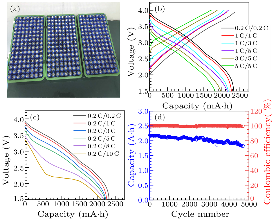
Fig. 1. (a) The high power 26650-type cylindrical NIBs. [(b), (c)] Charge-discharge curves at different rates of high power 26650-type cylindrical NIBs. (d) Cycle performance of high power 26650-type cylindrical NIBs at 2 C/2 C rate.
cpl-38-7-076501-fig2.png
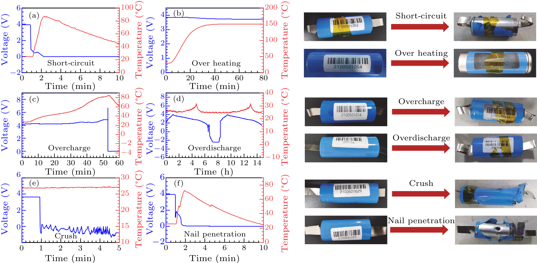
Fig. 2. The safety test results of high power 26650-type cylindrical NIBs at fully charged state. The voltage and temperature evolutions in the process of (a) external short-circuit test, (b) over heating test, (c) overcharge test, (d) overdischarge test, (e) crush tests, and (f) nail penetration test.
A safe NIB needs to go through the strict safety assessments based on the simulation of the above conditions. The effective safety assessments include safety testing (overcharge/discharge, external short-circuit, high temperature aging, etc.) and abuse testing (crush tests, nail penetration, fire, etc.). Taking the high power 26650-type cylindrical NIBs with a nominal capacity of 2300 mA$\cdot$h as an example, several tests were conducted on the fully charged batteries and the corresponding results are shown in Fig. 2. Firstly, the fully charged battery shows no fire and no smoke after a direct external short-circuit. The temperature rise due to the instantaneous release of electric energy [Fig. 2(a)] probably causes the electrolyte decomposition, which may further lead to gas expansion and the opening of the safety valve. Figure 2(b) shows the result of overheating test where the battery was heated to 150 ℃, but its voltage and surface temperature have no significant change during storage for 30 min at this temperature. In contrast, the battery temperature increased significantly after the overcharging test [Fig. 2(c)]. The main reason is that the high voltage induces the irreversible transformation of the cathode material structure and the decomposition of electrolyte, which leads to the increase of temperature. Moreover, the generated gas will open the battery safety valve, resulting in battery circuit break, voltage sudden drop and temperature decrease. Because of the adoption of aluminum foil collector, NIBs can be overdischarged without obvious temperature change, and the capacity can be recovered after continuous overdischarge [Fig. 2(d)]. Finally, both the crush and nail penetration tests reveal that no smoke and fire are observed even short circuit occurred inside the battery, and the highest surface temperature is lower than 80 ℃ after nail penetration [Figs. 2(e) and 2(f)]. Thus, no thermal runaway occurred during the above safety assessments, demonstrating the good safety of NIBs.
cpl-38-7-076501-fig3.png
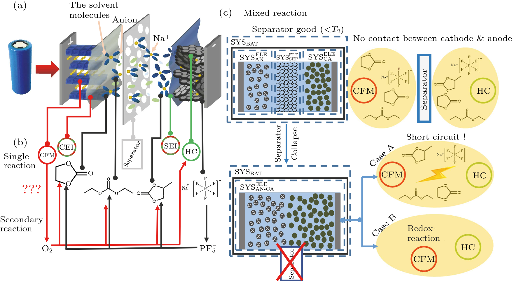
Fig. 3. Untangling the “reaction pathways” based on current understanding. (a) The working principle model of NIBs, with CFM |1 M NaPF$_{6}$/EC + PC + DEC|HC. (b) Single reactions for this battery chemistry, and secondary reactions caused by intermediate products generated from the single reactions. (c) Typical mixed reactions that occur under real world conditions. Further development may lead to the sharp temperature rise. The cases are categorized by the integrity of the separator.[18,35,38]
Characteristic Temperatures and Heat Generation Mechanism during Battery Thermal Runaway. In order to analyze the main heat source of high power 26650-type cylindrical NIBs in the process of thermal runaway, we refer to the thermal analysis of LIBs in the literature,[18,38] and design the thermodynamic model of NIBs as shown in Fig. 3, illustrating the basic thermodynamic systems and the design of calorimetric experiments. In this model, the battery is marked as ${\rm{SYS}}_{\rm{BAT}}$, which includes the porous anode (${\rm{SYS}}_{\rm{AN}}^{\rm{ELE}}$), the porous separator (${\rm{SYS}}_{\rm{SEP}}^{\rm{ELE}}$), and the porous cathode (${\rm{SYS}}_{\rm{CA}}^{\rm{ELE}}$).[18,38] Chemical and electrochemical reactions occur within the thermo dynamic system of the porous electrodes, without interference from other systems. Therefore, thermal tests at the materials level can be conducted by DSC, using powdered electrode materials with the respective electrolyte. Then, the battery is divided into four parts:[18] cathode +  electrolyte, anode + electrolyte, separator + electrolyte and cathode + anode. As shown in Fig. 3(a), each component in the battery has a unique failure behavior at extreme temperatures, which is denoted as the “single reaction” [Fig. 3(b)]. It becomes more complex when some highly reactive products, such as ${\rm{PF}}_{5}^{-}$, trigger the “secondary reactions”. The situation becomes even more complex due to the combination of reactions in the porous electrode in the real conditions, which are indicated as the “mixed reaction” in Fig. 3(c), making it difficult to design calorimetric tests to separate single or secondary reactions. The thermal behavior of the NIBs can also be divided into three stages, corresponding to three characteristic temperatures ($T_{1}$, $T_{2}$, $T_{3}$), which can be obtained by ARC test and are often used as the key parameters to characterize the battery thermal runaway features.[14,39,40] Batteries with a higher value of $T_{1}$ will be more stable at high temperature. $T_{2}$ is the triggering temperature of battery TR and the tipping point that separates the gradual temperature increase and the sharp temperature rise. $T_{2}$ is critical for evaluating battery safety, because a battery with higher $T_{2}$ will be more competent to pass safety tests, such as over heating or nail penetration. Now the quantitative definition of $T_{2}$ still requires further investigation. In this work, we chose that the threshold for determining $T_{2}$ is set by 10 ℃/min. $T_{3}$ is the maximum temperature reached by the battery during TR. ARC tests were performed on the fresh battery (100% SOH) and the aged battery (80% SOH) in full charged state following the flow in Fig. 4(a). The results for $T_{1}$, $T_{2}$, and $T_{3}$ parameters obtained from Fig. 4(b) are listed in Table 1 to compare the thermal behaviors of aged battery and fresh battery. There are obvious differences in the start temperature of exothermic reactions and the maximum temperature between aged and fresh batteries. It can be seen from Table 1 that $T_{1}$ of the aged battery is smaller than that of the fresh battery due to the poor stability of SEI. In addition, metallic Na plating will may occur on the surface of anode during aging,[41] resulting in exothermic reactions to occur in a lower temperature. The maximum temperature of thermal runaway represents the maximum energy release of NIBs to some extent. $T_{3}$ of the aged battery is lower than that of the fresh one, attributing to the lower energy stored in aged battery. Surprisingly, comparing with the LIBs using graphite as anode ($T_{1} < 100$ ℃, $T_{3}>400$ ℃, usually),[14,18,40] the NIBs have a higher onset temperature (110.14 ℃) of exothermic reaction, a lower maximum temperature (349.87 ℃) of thermal runaway.
Table 1. Key parameters of batteries with different SOH during thermal runaway process.
Batteries $T_{1}$ (℃) $T_{2}$ (℃) $T_{3}$ (℃)
100%SOH battery 110.14 198.46 349.87
80%SOH battery 101.82 186.53 276.15
cpl-38-7-076501-fig4.png
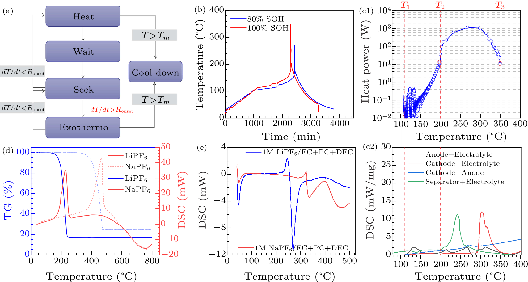
Fig. 4. (a) Heat-wait-seek (HWS) operating mode of ARC, where the Ronset is the set as 0.02 ℃/min, and the maximum test temperature is 350 ℃.[14,39] (b) The time-dependent temperature curves of ARC test of fresh and aged batteries. (c) Interpretation of the heat generation mechanisms. Comparison of the total heat generation power results from the ARC and DSC tests. (d) Comparison of the thermal stability of NaPF$_{6}$ and LiPF$_{6}$. (e) Comparison of the thermal stability of 1 M NaPF$_{6}$/EC + PC + DEC and 1 M LiPF$_{6}$/EC + PC + DEC.
It is worth mentioning that ${\rm{SYS}}_{\rm{SEP}}^{\rm{ELE}}$ generates less heat than its melting absorption, so the heat generation of ${\rm{SYS}}_{\rm{SEP}}^{\rm{ELE}}$ contributes little to the thermal runaway process and is not considered in further DSC analysis. By comparing the ARC curve of the battery and the DSC curve of each analysis system [Figs. 4(c1) and Fig. 4(c2)], we can easily find that the main source of heat between $T_{1}$ and $T_{2}$ is the anode decomposition in electrolyte, while the heat of cathode decomposition almost can be ignored. Thus, heat between $T_{1}$ and $T_{2}$ is mainly from the decomposition reaction of the anode. However, it is confused that both thermal powers are still insufficient to explain all that of the battery production, thereby it needs further exploration to the source of heat. In order to analyze the main heat source of NIBs in the range of $T_{2}$–$T_{3}$, the DSC curve of the mixed powder of cathode + anode was measured, as shown in Fig. 4(c2). It can be seen that the heat generation of cathode + anode is much higher compared with that of cathode + electrolyte and anode + electrolyte alone. This indicates that the additional heat source of NIBs in the process of $T_{2}$–$T_{3}$ may be due to the contact between the cathode and anode after the separator melts. The highly oxidizing cathode and the highly reducing anode underwent a redox reaction, which generated additional heat and pushed the battery temperature to $T_{3}$. Furthermore, it can be observed that the thermal decomposition of the fully charged CFM cathode is slight during $T_{2}$–$T_{3}$, indicating oxygen release may not happen during this process. We also compared the thermal stability of electrolyte salts of NIBs and LIBs separately, along with the electrolyte of the same formula at high temperature, as shown in Figs. 4(d) and 4(e). The results show that the decomposition temperature of pure NaPF$_{6}$ is about 220 ℃ higher than that of pure LiPF$_{6}$. At the same time, the NaPF$_{6}$ electrolyte has a better stability than LiPF$_{6}$ electrolyte in the same formula. Sodium salts and NIBs electrolytes show better thermal stability than lithium salts and LIBs electrolytes due to higher electrostatic energy in ionic crystals of salts (Madelung energy).[42] In Figs. 4(d) and 4(e), the thermal window of pure salt and electrolyte is very wide, far beyond the situation in the battery. As for solvents, the cyclic solvent molecules exhibit higher onset decomposition temperature than that of linear one, and co-solvents can reduce the heat release.[43] The thermal stability of organic electrolytes containing both salts and solvents is at the middle state between those of salts and solvents alone.[44,45] In a real situation where the electrolyte, electrode (sodiated state) and SEI coexist, the resulting metastable state may further narrow the thermal stability window. It is generally believed that SEI is mainly composed of inorganic layers and organic layers.[18] The thickness of these layers is usually between a few nanometers and tens of nanometers. The inner inorganic layer is connected to the electrode material, while the outer organic layer extends to the electrolyte. The inorganic layer consists mostly of some sodium inorganic substances, and the organic layer consists mostly of sodium containing organic substances formed by solvent molecules reacting with sodium. The typical SEI of NIBs mainly includes Na$_{2}$CO$_{3}$, Na$_{2}$O, NaF and other substances in the inorganic layer, and includes ROCO$_{2}$Na (R is an organic group) and polymer in the organic layer. Compared with the SEI of LIBs, that of NIBs has better thermal stability. This also proves that $T_{1}$ of NIBs is higher. Therefore, the high temperature stability of NIBs is better than that of LIBs to some extent. The high temperature will cause the SEI decomposing and producing gas. At the same time, the electrolyte will directly contact the exposed anode surface, which accelerates the side reaction. Under extreme conditions such as overheating and short-circuit, improving the stability of SEI will greatly improve the safety of the batteries. Some effective additives, such as fluoroethylene carbonate (FEC) or ethoxy(pentafluoro)cyclotriphosphazene (EFPN),[46,47] facilitate the thermal stability of carbonate electrolytes and even reduce their flammability by establishing a stable SEI. In summary, this work uses ARC and DSC to study the thermal runaway mechanisms of NIBs. Three characteristic temperatures ($T_{1}$, $T_{2}$, $T_{3}$) are analyzed to reveal features of battery thermal runaway. $T_{1}$ is caused by the side reactions at the anode and the thermal stability of the anode determines the initial temperature of thermal runaway. The redox reactions between the cathode and anode after the separator melts lead to intensive heat generation after the temperature reaches $T_{2}$, thus heating the battery from $T_{2}$ to $T_{3}$. The actual safety of the battery depends more on the anode and electrolyte, which is in line with the LIBs. Due to the characteristics of sodium compounds, NIBs have an initial decomposition temperature of more than 110 ℃, and their maximum thermal runaway temperature is also lower, showing good thermal stability. These results demonstrate that NIBs have better safety. In the future, the intrinsic safety characteristics of NIBs should be further explored.
cpl-38-7-076501-fig5.png
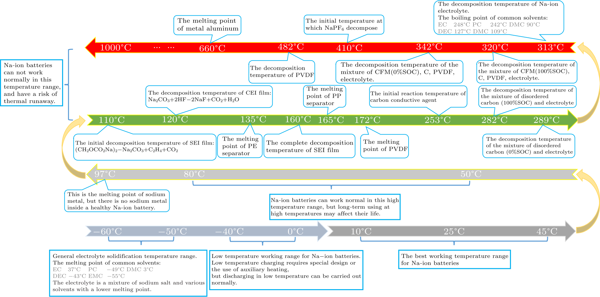
Fig. 5. The whole temperature characteristics of the NIBs from $-60$ ℃ to 1000 ℃.
In addition, we also summarized the whole temperature characteristics of the NIBs from $-60 $ ℃ to 1000 ℃, as shown in Fig. 5. However, the temperature of various side reactions in the NIBs with different specifications and electrochemical systems are not absolute, and the specific surface area of the active materials, the electrolyte formula, the SOC and SOH of battery will have a certain impact on the above results. With the development of the industrial application of NIBs, the safety of product (especially, thermal stability) will be the next important issue.[48] Besides electrolytes and electrode materials, the selections about separators, current collectors, binder, various functional additive materials etc. also have a significant influence for safety and thermal stability of NIBs, which also need to be further studied. In addition, we should also consider more safety additives with specific functions, including overcharge protection additives, thermal response materials, ceramic additives, flame retardant additives, special explosion-proof valves, etc. Further development of accurate characterization means is needed to capture detailed thermal parameters of the NIBs. At the same time, safety data on the accumulation of NIBs is still relatively lacking, where the whole life, 100% SOC range, abuse testing, different types of large capacity monomer (soft package, aluminum shell, cylinder etc.) and other aspects need to be systematically studied. It is urgent to establish targeted safety test standards of NIBs, meanwhile, a comprehensive and reliable safety failure analysis database of NIBs should be established to clarify the safety failure mechanism.
References Room-temperature stationary sodium-ion batteries for large-scale electric energy storageTuning the Closed Pore Structure of Hard Carbons with the Highest Na Storage CapacityA High-Temperature $\beta$-Phase NaMnO$_{2}$ Stabilized by Cu Doping and Its Na Storage PropertiesCorrelation Between Microstructure and Na Storage Behavior in Hard CarbonTailoring MXene-Based Materials for Sodium-Ion Storage: Synthesis, Mechanisms, and ApplicationsIntercalation chemistry of graphite: alkali metal ions and beyondHow Comparable Are Sodium-Ion Batteries to Lithium-Ion Counterparts?Temperature rise prediction of lithium-ion battery suffering external short circuit for all-climate electric vehicles applicationIn-operando high-speed tomography of lithium-ion batteries during thermal runawayThermal runaway features of large format prismatic lithium ion battery using extended volume accelerating rate calorimetryComparison of the Reactivity of Various Carbon Electrode Materials with Electrolyte at Elevated TemperatureExperimental Analysis of Thermal Runaway in 18650 Cylindrical Li-Ion Cells Using an Accelerating Rate CalorimeterProbing the heat sources during thermal runaway process by thermal analysis of different battery chemistriesTime Sequence Map for Interpreting the Thermal Runaway Mechanism of Lithium-Ion Batteries With LiNixCoyMnzO2 CathodeModel-based thermal runaway prediction of lithium-ion batteries from kinetics analysis of cell componentsThermal abuse performance of high-power 18650 Li-ion cellsUltralow-Concentration Electrolyte for Na-Ion BatteriesInvestigating the thermal runaway mechanisms of lithium-ion batteries based on thermal analysis databaseTemperature dependence of the passivation layer on graphiteCharacterisation of the ambient and elevated temperature performance of a graphite electrodeThermal Stability of the Solid Electrolyte Interface on Carbon Electrodes of Lithium BatteriesComparative thermal stability of carbon intercalation anodes and lithium metal anodes for rechargeable lithium batteriesInvestigations of the Exothermic Reactions of Natural Graphite Anode for Li-Ion Batteries during Thermal RunawayIn Situ Formation of a Stable Interface in Solid-State BatteriesRecent studies on the correlation between surface chemistry, morphology, three-dimensional structures and performance of Li and Li-C intercalation anodes in several important electrolyte systemsA General Discussion of Li Ion Battery SafetyAccelerating Rate Calorimetry Study on the Thermal Stability of Lithium Intercalated Graphite in Electrolyte. I. ExperimentalThermal Stability Studies of Li‐Ion Cells and ComponentsThermal stability of electrolytes with LixCoO2 cathode or lithiated carbon anodeA Novel Real-Time State-of-Health and State-of-Charge Co-Estimation Method for LiFePO 4 BatteryThermal stability of LixCoO2, LixNiO2 and λ-MnO2 and consequences for the safety of Li-ion cellsThermal Reactions Between Delithiated Lithium Nickelate and Electrolyte SolutionsThermal stability of LixCoO2 cathode for lithium ion batteryTemperature-Dependent Dynamic Properties of Li x Mn 2 O 4 in Monte Carlo SimulationsRegulating Pore Structure of Hierarchical Porous Waste Cork‐Derived Hard Carbon Anode for Enhanced Na Storage PerformanceMaterials for lithium-ion battery safetyAbuse by External Heating, Overcharge and Short Circuiting of Commercial Lithium-Ion Battery CellsProbing Thermal and Chemical Stability of Na x Ni 1/3 Fe 1/3 Mn 1/3 O 2 Cathode Material toward Safe Sodium-Ion BatteriesThe Thermal Stability of Lithium Solid Electrolytes with Metallic LithiumThermal Runaway of Lithium-Ion Batteries without Internal Short CircuitDegradation mechanism of over-charged LiCoO2/mesocarbon microbeads battery during shallow depth of discharge cyclingComprehensive Insights into the Reactivity of Electrolytes Based on Sodium IonsIn search of an optimized electrolyte for Na-ion batteriesFailure analysis with a focus on thermal aspect towards developing safer Na-ion batteriesAdvances in materials for all‐climate sodium‐ion batteriesThermal stability of Sn anode material with non-aqueous electrolytes in sodium-ion batteriesNonflammable electrolyte for safer non-aqueous sodium batteriesA New Emerging Technology: Na‐Ion Batteries
[1] Pan H, Hu Y S, and Chen L 2013 Energy & Environ. Sci. 6 2338
[2] Meng Q, Lu Y, Ding F, Zhang Q, Chen L, and Hu Y S 2019 ACS Energy Lett. 4 2608
[3] Jiang L, Lu Y, Wang Y, Liu L, Qi X, Zhao C, Chen L, and Hu Y S 2018 Chin. Phys. Lett. 35 048801
[4] Zhang B, Camélia M, Christel L, Cathie V G, and Tarascon J M 2016 Adv. Energy Mater. 6 1501588
[5] Lei Y, Yan Z, Lai W, Chou S, Wang Y, Liu H, and Dou S 2020 Electrochem. Energy Rev. 3 766
[6] Li Y, Lu Y, Adelhelm P, Titirici M M, and Hu Y S 2019 Chem. Soc. Rev. 48 4655
[7] Abraham K M 2020 ACS Energy Lett. 5 3544
[8] Chen Z, Xiong R, Lu J, and Li X 2018 Appl. Energy 213 375
[9] DP F, Scheel M, JB R, Tjaden B, Hunt I, and TJ M 2015 Nat. Commun. 6 6924
[10] Feng X, Fang M, He X, Ouyang M, Lu L, Wang H, and Zhang M 2014 J. Power Sources 255 294
[11] MacNeil D D, Larcher D D, and Dahn J R 2019 J. Electrochem. Soc. 146 3596
[12] Lei B, Zhao W, Ziebert C, Uhlmann N, Rohde M, and Seifert H 2017 Batteries 3 14
[13] Zheng S, Wang L, Feng X, and He X 2018 J. Power Sources 378 527
[14] Feng X, Zheng S, He X, Wang L, Wang Y, and Ren D 2018 Front. Energy Res. 6 126
[15] Ren D, Liu X, Feng X, Lu L, Ouyang M, and Li J 2018 Appl. Energy 228 633
[16] Roth E P and Doughty D H 2004 J. Power Sources 128 308
[17] Li Y, Yang Y, Lu Y, Zhou Q, Qi X, Meng Q, Rong X, Chen L, and Hu Y S 2020 ACS Energy Lett. 5 1156
[18] Feng X, Zhen S, Ren D, He X, Wang L, Cui H, Liu X, Jin C, Zhang F, Xu C, Hsu H, Gao S, Chen T, Li Y, Wang T, Wang H, Li M, and Ouyang M 2019 Appl. Energy 246 53
[19] Andersson A M, Edstrom K, Rao N, and Wendsjö Å 1999 J. Power Sources 81–82 286
[20] Andersson A M, Edstrom K, and Thomas J O 1999 J. Power Sources 81–82 8
[21] Lee H, W, and Wang Y 2004 J. Electrochem. Soc. 151 A542
[22] Sacken U, Nodwell E, Sundher A, and Dahn J 1995 J. Power Sources 54 240
[23] Yang H, Bang H, Amine K, and Prakash J 2005 J. Electrochem. Soc. 152 A73
[24] Liu L, Qi X, Yin S, Zhang Q, Liu X, Suo L, Li H, Chen L, and Hu Y S 2019 ACS Energy Lett. 4 1650
[25] Aurbach D, Zaban A, Ein-Eli Y, Weissman I, Chusid O, Markovsky B, Levi M, Levi E, Schechter A, and Granot E 1997 J. Power Sources 68 91
[26] Doughty D and Roth E P 2012 Electrochem. Soc. Interface 21 37
[27] Richard M and Dahn J R 1999 J. Electrochem. Soc. 146 2068
[28] Maleki H, Deng G, Anani A, and Howard J 1999 J. Electrochem. Soc. 146 3224
[29] Yamaki J, Baba Y, Katayama N, Takatsuji H, Egashira M, and Okada S 2003 J. Power Sources 119–121 789
[30] Qiao R, Zhang M, Liu Y, Ren W, Lin Y, and Pan F 2016 Chin. Phys. Lett. 33 078201
[31] Dahn J R, Fuller E W, Obrovac M, and Vonsacken U 1994 Solid State Ionics 69 265
[32] Arai H, Tsuda M, Saito K, Hayashi M, and Sakurai Y 2002 J. Electrochem. Soc. 149 A401
[33] Baba Y, Okada S, and Yamaki J 2002 Solid State Ionics 148 311
[34] Ouyang C, Shi S, Wang Z, Li H, Huang X, and Chen L 2005 Chin. Phys. Lett. 22 489
[35] Li Y, Lu Y, Meng Q, Jensen A, Zhang Q, Zhang Q, Tong Y, Qi Y, Gu L, Titirici M M, and Hu Y S 2019 Adv. Energy Mater. 9 1902852
[36] Liu K, Liu Y, Lin D, Pei A, and Cui Y 2018 Sci. Adv. 4 eaas9820
[37] Larsson F and Mellander B E 2014 J. Electrochem. Soc. 161 A1611
[38] Xie Y, Xu G, Che H, Wang H, Yang K, Yang X G F, Yang R, Che Z, and Khalil A 2018 Chem. Mater. 30 4909
[39] Chen R, Nolan A M, Lu J, Chen L, Huang X, and Li H 2020 Joule 4 812
[40] Liu X, Ren D, Hsu H, Feng X, GL X, Zhuang M G H, Lu L, Han X, Chu Z, Li J, He X, Amine K, and Ouyang M 2018 Joule 2 2047
[41] Zhang L, Ma Y, Cheng X, Cui Y, Guan T, Gao Y, Du C, Yin G, Lin F, and Nordlund D 2016 J. Power Sources 329 255
[42] Eshetu G G, Grugeon S, Kim H, Jeong S, Wu L, Gachot G, Laruelle S, Armand M, and Passerini S 2016 ChemSusChem 9 462
[43] Ponrouch A, Marchante E, Courty M, Tarascon J M, and Palacín M R 2012 Energy & Environ. Sci. 5 8572
[44] Li Y, Lu Y, Chen L, and Hu Y S 2020 Chin. Phys. B 29 048201
[45] Zhu X B and Wang L Z 2020 EcoMat 2 e12043
[46] Lee Y, Lim H, Kim S O, Kim H S, Kim K J, Lee K Y, and Choi W 2018 J. Mater. Chem. A 6 20383
[47] Feng J, An Y, Ci L, and Xiong S 2015 J. Mater. Chem. A 3 14539
[48] Hu Y S, Komaba S, Forsyth M, Johnson C, and Rojo T 2019 Small Methods 3 1900184