Chinese Physics Letters, 2020, Vol. 37, No. 12, Article code 127501 Low Voltage Reversible Manipulation of Ferromagnetic Resonance Response in CoFeB/HfO$_{2}$ Heterostructures Yangping Wang (汪样平)1,2, Hongyan Zhou (周红燕)3, Yibing Zhao (赵逸冰)1,2, Fufu Liu (刘福福)1,2, and Changjun Jiang (蒋长军)1,2* Affiliations 1Key Laboratory for Magnetism and Magnetic Materials (Ministry of Education), Lanzhou University, Lanzhou 730000, China 2Key Laboratory of Special Function Materials and Structure Design (Ministry of Education), Lanzhou University, Lanzhou 730000, China 3Institute of Electronic Materials, Lanzhou University, Lanzhou 730000, China Received 23 August 2020; accepted 3 November 2020; published online 8 December 2020 Supported by the National Natural Science Foundation of China (Grant Nos. 51671099 and 11974149), the Open Foundation Project of Jiangsu Key Laboratory of Thin Films (Grant No. KJS1745), the Program for Changjiang Scholars and Innovative Research Team in University (Grant No. IRT-16R35), and the Fundamental Research Funds for the Central Universities.
*Corresponding author. Email: jiangchj@lzu.edu.cn
Citation Text: Wang Y P, Zhou H Y, Zhao Y B, Liu F F, and Jiang Z J 2020 Chin. Phys. Lett. 37 127501    Abstract We report that the ferromagnetic resonance (FMR) response of the CoFeB/HfO$_{2}$ heterostructures is stabilized and reversibly manipulated by ionic gel. Ionic gel with excellent flexibility is used as a medium to form an electric field. When a 4 V gate voltage is applied, the resonance field $H_{\rm r}$ and peak-to-peak linewidth $\Delta H_{\rm pp}$ at different angles are regulated. When $\theta = 20^{\circ}$, the $H_{\rm r}$ is regulated up to 82 Oe. When $\theta = 70^{\circ}$, $\Delta H_{\rm pp}$ is tuned up to 75 Oe. When the gate voltage is repeatedly applied, the FMR spectra can be freely switched between the initial state and the gated state. Our study provides an effective method to manipulate the damping of the magnetic film stably and reversibly. DOI:10.1088/0256-307X/37/12/127501 PACS:75.85.+t, 75.78.-n, 75.78.Jp © 2020 Chinese Physics Society Article Text The current-induced spin-orbit torque (SOT) realization of the magnetized reversal is the basis for designing spin-orbit torque magnetic random access memory (MRAM). For future practical applications of SOT-MRAM, it not only requires the accuracy, ultra-fast and non-volatility of data storage,[1,2] but also needs to achieve low energy consumption.[3–5] Reducing the writing current density $J_{\rm c}$ can directly and effectively reduce the energy consumption of MRAM.[6] However, the critical writing current density is closely related to the damping of the material. Damping is a nonlinear spin relaxation phenomenon of magnetization precession.[7] Lower damping can reduce the writing current.[8] For commercial application devices, it is expected that the amplitude of the damping can be manipulated reversibly. Woltersdorf et al.[9] changed the damping parameters of Ni$_{80}$Fe$_{20}$ thin films by two orders of magnitude via doping heavy rare earth elements. Ganguly et al.[10] used Ga$^{+}$ irradiation to change the damping of NiFe/Pt bilayers. However, these methods of regulating damping are irreversible. Moreover, Mondal et al.[11] realized the reversible manipulation of damping by the spin current-induced spin torque in CoFeB/W heterostructures. Nevertheless, the Joule heat generated by the spin current-induced spin torque is undesirable. Therefore, it is necessary to find another method of reversibly controlling damping. According to reports, ferroelectric gating has realized the manipulation of ferromagnetic resonance (FMR) spectroscopy.[7] This means that the damping can be directly and reversibly controlled by the magnetoelectric coupling effect. However, the higher gate voltage is not satisfactory. Recently, it has been frequently reported that ionic liquid gating regulates the magnetic properties of thin films.[12–15] Compared with the ferroelectric gating, it greatly reduces the regulated gate voltage, which provides an effective way to design low-power devices. Therefore, in this work, we use ionic gel to manipulate the FMR spectra of CoFeB films. The test results show that both the resonance field $H_{\rm r}$ and the peak-to-peak linewidth $\Delta H_{\rm pp}$ can be adjusted. Furthermore, the CoFeB film is a kind of important spintronic materials, which is widely used in the material system of current-induced magnetization reversal.[6,11,16–18] This is of great significance for designing low energy consumption spintronic devices. At room temperature, the ferromagnetic layer CoFeB (7 nm) and the cap layer HfO$_{2}$ (3 nm) were deposited on a silicon substrate by magnetron sputtering when the basic vacuum was less than $5\times 10^{-5}$ Pa. To test the FMR spectra, the sample was cut into $2 \times 2$ mm squares. The FMR spectra were measured by electron spin resonance (ESR, JEOL, JES-FA300). The test power was 1 mW and the test frequency was about 9 GHz. Poly(vinylidene fluoride-co-hexafluoropropylene) [P(VDF-HFP)] and N,N-diethyl-N-(2-methoxyethyl)-N-methylammonium bis (trifluororomethylsulphonyl) imide (DEME-TFSI) were dissolved in acetone solution and stirred with a magnetic stirrer for more than two hours to get a clear and transparent mixture solution. The mass ratio of P(VDF-HFP), DEME-TFSI, and acetone were $1\!:\!4\!:\!5$. Then, the homogeneous solution was spin-coated on the quartz glass. After drying for 16 hours in a vacuum oven at 160℃, the flexible ionic gel was prepared.[19–21]
cpl-37-12-127501-fig1.png
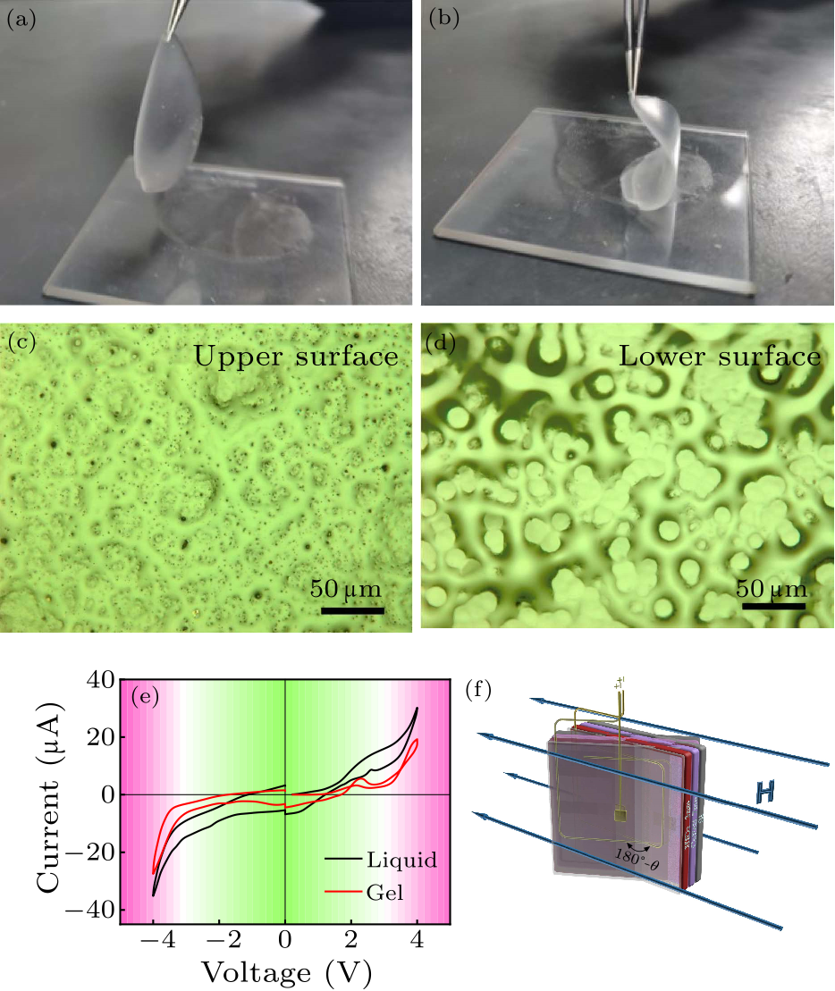
Fig. 1. Photograph of ionic gel when (a) upright and (b) bent. Photographs of the (c) upper and (d) lower surfaces of the ionic gel taken by an optical microscope. (e) The current-voltage ($I$–$V$) curves for ionic gel and ionic liquid. (f) Schematic diagram of in situ ferromagnetic resonance testing.
Figure 1(a) shows the prepared ionic gel. Lifting gently, the ionic gel can be fully extended vertically. Even if it was bent, it would not break, as shown in Fig. 1(b). This indicates that the ionic gel has excellent flexibility. The ionic gel was allowed to stand for more than 48 hours. An optical microscope was used to observe its surface. Many dense holes can be observed on the upper surface, as shown in Fig. 1(c). These holes can both store ionic liquids and act as channels for the movement of anions and cations. A large amount of ionic liquid can be observed on the lower surface, as shown in Fig. 1(d). This result is caused by the ionic liquid moving downward due to gravity during long-term storage. It ensures good adhesion between the ionic gel and the film. Figure 1(e) shows the current-voltage ($I$–$V$) curves of ionic liquid and ionic gel. The trends of the two $I$–$V$ curves are very similar, and the current is on the same order of magnitude. This indicates that the ionic liquid and the ionic gel have the same degree of charge accumulation. That is to say, while the ionic liquid is stored in the ionic gel, the characteristic of the ionic liquid to form a high electric field is not destroyed. During the test, the ionic gel and the film were tightly bonded together using tape. The test device is shown in Fig. 1(f). The cap layer HfO$_{2}$ can not only separate the ionic gel and CoFeB layer, but also increase the electric field of the electric double layer (EDL) at the interface.[22] Figure 2(a) depicts the FMR spectra for different angles before applying the gate voltage. As the angle increases, the $H_{\rm r}$ gradually increases. This indicates that the axis of easy magnetization is parallel to the film surface, while the axis of hard magnetization is perpendicular to the film surface.[23] Figure 2(b) describes the FMR spectra for different angles after applying the gate voltage. The resonance field increases with the angle, which is not changed before and after the gate voltage is applied. This indicates that the application of gate voltage does not change the magnetic anisotropy of the film. Figures 2(c) and 2(d) depict the FMR spectra changes before and after the gate voltage is applied when $\theta = 0^{\circ}$ and $\theta = 70^{\circ}$, respectively. After the gate voltage is applied, the FMR spectra drift toward the low magnetic field, and the $\Delta H_{\rm pp}$ is also tuned by the electric field.
cpl-37-12-127501-fig2.png
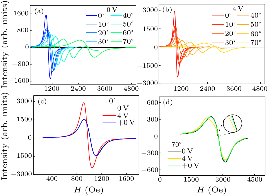
Fig. 2. (a) The initial FMR spectra when the angle between the magnetic field direction and the film plane gradually increases. (b) FMR spectra at different angles when the gate voltage is 4 V. The FMR spectra before and after the gate voltage are applied when the angle between the magnetic field direction and the film surface is (c) 0$^{\circ}$ and (d) 70$^{\circ}$.
To obtain high accuracies of $H_{\rm r}$ and $\Delta H_{\rm pp}$, the FMR spectra are integrated. Then the asymmetric Lorentz function $\xi (H) = A[\Delta H_{\rm pp}\cos\delta+(H-H_{\rm r})\sin\delta]/[{\Delta H}_{\rm pp}^{2}+(H-H_{\rm r})^{2}]$ is used to fit the integral spectra,[7,24] where $H$ is the external magnetic field, $A$ is the integral coefficient, and $\delta$ is the phase difference between the real and imaginary parts of the dynamic susceptibility. We define $H_{\rm r,shift}=H_{\rm r,initial} - H_{\rm r,4V}$ and $\Delta H_{\rm pp,shift}=\Delta H_{\rm pp,initial}-\Delta H_{\rm pp,4V}$. When the magnetic field direction is parallel to the film, the $H_{\rm r}$ drifts by 40 Oe, and the $\Delta H_{\rm pp}$ is regulated by 50 Oe. The information that $H_{\rm r}$ and $\Delta H_{\rm pp}$ are regulated from different angles is summarized in Fig. 3. After applying the gate voltage, the $H_{\rm r}$ drift is always in the low magnetic field direction. When $\theta = 20^{\circ}$, the $H_{\rm r}$ is tuned up to 82 Oe. However, the regulation of $\Delta H_{\rm pp}$ by gate voltage is more complicated. Generally, the $\Delta H_{\rm pp}$ of the FMR spectra can be expressed as $\Delta H_{\rm pp} = \Delta H_{\rm Gil} +\Delta H_{\rm inh} + \Delta H_{\rm TMS}$,[25–27] where $\Delta H_{\rm Gil}$ is the linewidth due to intrinsic Gilbert damping, $\Delta H_{\rm inh}$ is the inhomogeneous broadening, and $\Delta H_{\rm TMS}$ represents the contribution of two-magnon scattering to the linewidth. When $\theta < 30^{\circ}$, the $\Delta H_{\rm pp}$ becomes smaller. When $\theta > 30^{\circ}$, the $\Delta H_{\rm pp}$ becomes larger. This means that the damping of the film can be modulated to make it larger or smaller by applying a gate voltage. When $\theta = 70^{\circ}$, the $\Delta H_{\rm pp}$ is adjusted up to 75 Oe. Finally, the stability of the ionic gel to regulate the FMR response was tested, and the test results are presented in Fig. 4. By repeatedly applying the gate voltage, the FMR spectra can be switched freely between the initial state and the gated state, as depicted in Fig. 4(a). The repeatedly controlled mapping is described in Fig. 4(b). The intensity of the FMR spectra is expressed in red when it is greater than zero, and expressed in blue when it is less than zero. Figures 4(c) and 4(d) show that the gate voltage has a stable regulation effect on the $H_{\rm r}$ and the $\Delta H_{\rm pp}$. This fully proves that the damping of the CoFeB thin film can be regulated stably by ionic gel.
cpl-37-12-127501-fig3.png
Fig. 3. (a) Angular dependence of the resonance field ($H_{\rm r}$) for the initial state (0 V), the gated state (4 V), and the state back to 0 V from 4 V (+0 V). The purple curve shows the dependence of the $H_{\rm r,shift}$ on an angle. (b) Angular dependence of the peak-to-peak linewidth ($\Delta H_{\rm pp}$) for the initial state (0 V), the gated state (4 V), and the state back to 0 V from 4 V (+0 V). The orange curve shows the dependence of the $\Delta H_{\rm pp,shift}$ on an angle.
cpl-37-12-127501-fig4.png
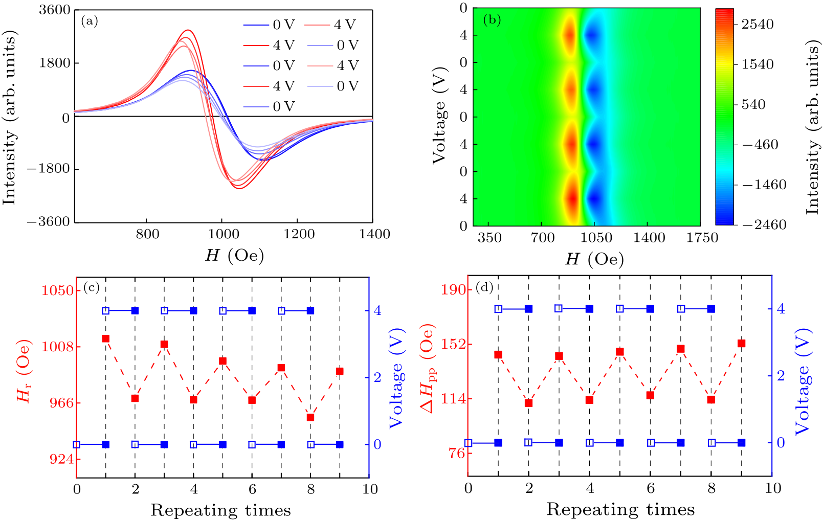
Fig. 4. (a) The FMR spectra tested when the gate voltage is repeatedly applied. (b) The mapping diagram of the FMR spectra when the gate voltage is repeatedly applied. Regulation diagram of (c) $H_{\rm r}$ and (d) $\Delta H_{\rm pp}$ by applying gate voltage repeatedly.
In conclusion, we have investigated the ionic-gel-mediated FMR response of CoFeB/HfO$_{2}$ heterostructures. Ionic gel with good flexibility is successfully prepared. Using the sandwich test structure, the $H_{\rm r}$ and $\Delta H_{\rm pp}$ are stably and reversibly regulated. When $\theta = 20^{\circ}$, the $H_{\rm r}$ is regulated up to 82 Oe. When $\theta =70^{\circ}$, the $\Delta H_{\rm pp}$ is tuned up to 75 Oe. In addition, because the linewidth of the FMR spectra contains damping information, it is fully proved that the damping of the magnetic film can be stabilized and reversibly regulated by the electric field. This work further paves the way to design of low-energy spintronic devices.
References Perpendicular switching of a single ferromagnetic layer induced by in-plane current injectionEnergy‐Efficient Ultrafast SOT‐MRAMs Based on Low‐Resistivity Spin Hall Metal Au 0.25 Pt 0.75A spin–orbit torque switching scheme with collinear magnetic easy axis and current configurationField-free spin-orbit torque switching of composite perpendicular CoFeB/Gd/CoFeB layers utilized for three-terminal magnetic tunnel junctionsStructural absorption by barbule microstructures of super black bird of paradise feathersEnhancement of spin–orbit torque via interfacial hydrogen and oxygen ion manipulationElectric tuning of magnetization dynamics and electric field-induced negative magnetic permeability in nanoscale composite multiferroicsControl of damping in perpendicularly magnetized thin films using spin-orbit torquesDamping by Slow Relaxing Rare Earth Impurities in Ni 80 Fe 20 Tunable Magnetization Dynamics in Interfacially Modified Ni81Fe19/Pt Bilayer Thin Film MicrostructuresAll-optical detection of the spin Hall angle in W / CoFeB / SiO 2 heterostructures with varying thickness of the tungsten layerLow-Voltage-Manipulating Spin Dynamics of Flexible Fe 3 O 4 Films through Ionic Gel Gating for Wearable DevicesIonic liquid gating control of magnetic anisotropy in Ni0.81Fe0.19 thin filmsIonic-liquid gating of perpendicularly magnetised CoFeB/MgO thin filmsControl of magnetic anisotropy in Pt/Co system using ionic liquid gatingCharacterization and Manipulation of Spin Orbit Torque in Magnetic HeterostructuresElectric-Field Control of Spin-Orbit Torques in Perpendicularly Magnetized W / CoFeB / MgO FilmsCurrent‐Induced Spin–Orbit Torques for Spintronic ApplicationsTuning the metal-insulator crossover and magnetism in SrRuO3 by ionic gatingA pressure sensitive ionic gel FET for tactile sensingLow-Voltage Control of (Co/Pt) x Perpendicular Magnetic Anisotropy Heterostructure for Flexible SpintronicsElectrical control of magnetism in oxidesVoltage Control of Magnetic Anisotropy through Ionic Gel Gating for Flexible SpintronicsStrong Nonvolatile Magnon-Driven Magnetoelectric Coupling in Single-Crystal Co / [ PbMg 1 / 3 Nb 2 / 3 O 3 ] 0.71 [ PbTiO 3 ] 0.29 HeterostructuresThickness and angular dependent ferromagnetic resonance of ultra-low damping Co 25 Fe 75 epitaxial filmsInterplay of large two-magnon ferromagnetic resonance linewidths and low Gilbert damping in Heusler thin filmsAnomalously large ferromagnetic resonance linewidth in the Gd/Cr/Fe film plane
[1] Miron I M et al. 2011 Nature 476 189
[2] Zhu L et al. 2020 Adv. Electron. Mater. 6 1901131
[3] Fukami S, Anekawa T, Zhang C and Ohno H 2016 Nat. Nanotechnol. 11 621
[4] Chen J Y et al. 2017 Appl. Phys. Lett. 111 012402
[5] Chen X et al. 2018 Nat. Commun. 9 1
[6] Peng W L et al. 2019 Appl. Phys. Lett. 115 092402
[7] Jia C et al. 2015 Sci. Rep. 5 11111
[8] Saha S et al. 2020 Phys. Rev. B 101 224401
[9] Woltersdorf G et al. 2009 Phys. Rev. Lett. 102 257602
[10] Ganguly A et al. 2015 Sci. Rep. 5 17596
[11] Mondal S et al. 2017 Phys. Rev. B 96 054414
[12] Hou W et al. 2019 ACS Appl. Mater. & Interfaces 11 21727
[13] Li C et al. 2020 Curr. Appl. Phys. 20 883
[14] Liu Y T et al. 2016 J. Appl. Phys. 120 023901
[15] Hirai T et al. 2016 Appl. Phys. Express 9 063007
[16] Qiu X et al. 2018 Adv. Mater. 30 1705699
[17] Filianina M et al. 2020 Phys. Rev. Lett. 124 217701
[18] Ryu J, Lee S, Lee K J and Park B G 2020 Adv. Mater. 32 1907148
[19] Yi H T et al. 2014 Sci. Rep. 4 6604
[20] Yamada S, Sato T and Toshiyoshi H 2017 Appl. Phys. Lett. 110 253501
[21] Zhao S et al. 2018 ACS Nano 12 7167
[22] Song C et al. 2016 Chin. Phys. B 25 067502
[23] Wang C et al. 2018 ACS Appl. Mater. & Interfaces 10 29750
[24] Zhou C et al. 2018 Phys. Rev. Appl. 9 014006
[25] Cheng Y et al. 2018 Appl. Phys. Lett. 113 262403
[26] Peria W K et al. 2020 Phys. Rev. B 101 134430
[27] Sun L et al. 2018 J. Magn. Magn. Mater. 451 480